
Summary of Contents for C2STek FL-2000G
- Page 1 FL-2000G User Manual (Multi-functional AVL Terminal) Ver:1.0 Copyright © 2011 Shenzhen C2S Technology Co., Ltd. All rights reserved.
-
Page 2: Table Of Contents
Contents Index 1 INTRODUCTION ..........................4 1.1Attention ............................4 1.2 Instructions of safety ........................4 1.3 About document ..........................5 2 BASIC DESCRIPTION ........................5 2.1 Package contents ..........................5 2.2 Add-ON Optional Accessories ....................... 6 2.2.1 Part Name: Mobile Data Terminal for GPS AVL ..............6 2.2.2 Part Name: Liquid Fuel Level Sensor .................. - Page 3 7.1.8 Setup GPRS parameters: ....................... 35 7.1.9 Setup Time-based Data report Interval: (GPRS) ..............36 7.1.10 Switch Off Time-based data report: ..................36 7.1.11 Switch ON/OFF GPRS Data report when ACC Off ............36 7.1.12 Setup Voice listen-in Call Back telNo................36 7.1.13 Setup Distance Report Parameter: ..................
-
Page 4: Introduction
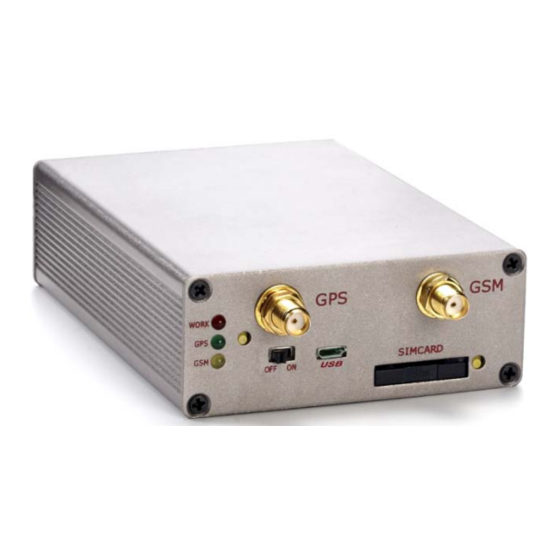
The device uses a 9V...36V DC power supply. The allowed range of voltage is 9V...36V DC Power. To avoid mechanical damage, it is advised to transport the FL-2000G device in an impact-proof package. Before usage, the device should be placed so that its LED indicators are visible, which show the status of operation the device is in. -
Page 5: About Document
. SMS – Short Message Service. . AC/DC – Alternating Current/Direct Current. . Record – AVL data stored in FL-2000G memory. AVL data contains GPS and I/O information . AVL packet - Data packet that is being sent to server during data transmission. -
Page 6: Add-On Optional Accessories
SOS Button 2.2 Add-ON Optional Accessories 2.2.1 Part Name: Mobile Data Terminal for GPS AVL Part No.: PND-100 • 3.5’ TFT LCD Touch Display, 320*240 • Microsoft WinCE.NET 5.0 • SD Card Supported: 128MB-8GB • Size:163x74.3x26.6mm Functionality: Road Navigation with Map Software Make calls out and pickup incoming call Receive/Send SMS to anyone GPRS Message Communication with GPS monitoring Center... -
Page 7: Part Name: Rs485 Image Camera
2.2.3 Part Name: RS485 Image Camera Part No.: ZM-CAM-ICA01 • Dimension: 93.5 (Diameter)x60.5mm(Height) • Work Temp:-20 ~70 • Resolution: 320x240Pixels( 18 IR LEDs) • Image Output: JPEG • View Angle: 90Degrees • Baud Rate:115200 • Communication: RS232 • Night-Vision Distance:5-10Meters •... -
Page 8: Part Name: Speed Over Alarm Buzzer
2.2.5 Part Name: Speed Over Alarm Buzzer Part NO.: HYDZ • Working Voltage: 3-24V DC • Sound at 10CM: 90dB • Rated Current: 15mA • Beeping Type: Bi….Bi….Bi 2.2.6 Part Name.: Temperature Sensor Part NO.: ST0923971 Notice: The Camera/RFID reader is sharing one same RS232 Port. So it cannot be connected with both accessories at the same time. -
Page 9: Gps Features
2.3.2 GPS features: . Ublox GPS Receiver . -160dB Sensitivity 2.3.3Hardware features: . ARM7 STM103FRBT6 Micro Controller . 4MB internal memory . Built-in high sensitivity movement Sensor . Internal backup battery .On board RS232 or 485 communication port .Two Way Audio intercom .Fuel Sensor, Temperature Sensor, Dispatch LCD Display connection 2.3.4 Interface features: . -
Page 10: Connection, Pinout, Accessories
3 CONNECTION, PINOUT, ACCESSORIES 3.1 Status LED 3.2 Wire Connection PIN out Introduction Copyright © 2011 Shenzhen C2S Technology Co., Ltd. All rights reserved. -
Page 11: Onboard Pin Slot Description
3.2.1 OnBoard Pin Slot description - L1 2x9 Pin Socket (Power+I/O) Standard 2x9 socket Pin Slot Description: Pin No. Pin Name Description MIC+ Microphone + SOS - Digital Output, Connection with Relay for Immobilizer On/Off Duty/Empty Digital Input, 0V: empty, Positive: Duty Door Unlock Digital Output for Door Unlock operation Buzzer... - Page 12 2x4Pin socket Description: Pin No. Pin Name Description 5V DC Power Output, 5V DC (Backup for other application) RS232, TX GPS Data GPS Receiver Raw GPS data output Output Speaker + Speaker+ for Display 12/24V DC Power Output 12/24V DC for Display Fuel AD Calibration output, Range 0-9V DC Temperature sensor Input(0-10VDC) Speaker -...
-
Page 13: Insert Simcard
3.3 Insert SIMCARD ① Using screwdriver to SIM card Slot spring up button ② Slide out the lid ③ Put the SIM card to the socket ④ Slid back the lid with SIM card to slot. 3.4 Internal battery switch This switch is designed for switch ON/Off internal backup battery. - Page 14 FL-2000G Device. The driver you can download from http://www.c2stek.com/en/Download.aspx When FL-2000G is connected for the first time to PC, you will be prompted with 'Found New Hardware' window. Click 'Cancel' to stop automatic installation process and disconnect FL-2000G from PC.
- Page 15 After above step, you have installed the driver in your PC successfully. Now connect the FL-2000G device to PC, normally the system will not prompt for install a driver any more. It will recognize by the PC automatically. If you are still prompted by the system, you can follow the PC prompt and direct the driver location as you have selected in above process.
-
Page 16: Wire Connection And Accessories
PC and reinstall the drivers. 3.6 Wire Connection and Accessories For installation this FL-2000G device to a vehicle, Please refer to “FL-2000G Installation Wiring Diagram” which you can download from support center. For those special application accessories like Fuel Monitoring, Temperature monitoring, Camera Image and RFID reader etc, please refer to those dedicated instruction document which will be Copyright ©... -
Page 17: Firmware
More detail operations please refer to “FL-2000G Firmware Upgrading Instruction” document. 5 OPERATIONAL BASICS 5.1 Operational Principals FL-2000G device is designed to acquire GPS and I/O information in live and send them to server Copyright © 2011 Shenzhen C2S Technology Co., Ltd. All rights reserved. -
Page 18: Sleep Mode
" FL-2000G Air Traffic Communication protocol' document. The FL-2000G can be managed by SMS Commands also. SMS command list is described in SMS command list section. Module configuration can be performed over TCP, or via SMS, or via ComPort configurator software tool. -
Page 19: Movement Sensor
Instead, it uses virtual points which are established every second, and calculates distance between them. This virtual odometer for FL-2000G need to activate by GPRS commands and then it will begin to start the odometer calculation. And it also could be deactivated by GPRS commands. -
Page 20: Speed Limit Over And Buzzer Alert
This time period only can be configured from Server Client software remotely. 5.8 GEO Fencing: FL-2000G device allow user to configure 10 GEO Fencing areas. And the fencing area could be circle or rectangle shape. Copyright © 2011 Shenzhen C2S Technology Co., Ltd. All rights reserved. -
Page 21: Alarm Working Principals
• Y – Circular Point Y coordinate • R – radius of circle when Circular zone used 5.9 Alarm working principals FL-2000G is a dedicated AVL tracking terminal, but we also included alarm functions for security purpose. FL-2000G alarm function includes: - External Power tampers alarm - Panic Help alarm - Shortcut Call button for Medical, Information query service help with Monitoring base. -
Page 22: Configurations
All above alarms can be enable/disable by configurator software, and the user could use configurator to choose the wanted alert method like by SMS, missed calls etc. 6 CONFIGURATIONS FL-2000G has default factory settings. Setting should be changed according to your application and GSM operator information. FL-2000G configuration could be performed with multi-method:... -
Page 23: Operation Menus
FL-2000G Configurator window consist of following part: ① -Operation Menu; ② - GPRS Parameters Setting ③ - Authorization Setting ④ - Device Status display ⑤ - System Setting ⑥ - Other Setting 6.1.1 Operation Menus: • Default: Choose the default factory recommended settings for the device. -
Page 24: Gprs Parameters
Configurator is able to read it. Otherwise it will be displayed as 'none'. • COM port: Click this drop-down list to choose which COM port is used by FL-2000G to connect to PC. See chapter 0 to find out number of the port. -
Page 25: Authorization Setting
• Port1(2): This is destination server port number to which FL-2000G is sending data using GPRS. FL-2000G support device configure two Ports. Port1 is for IP1 only, and Port 2 for IP2 only. The priority is same as the IP address. -
Page 26: Device Status
" invalid Format" 6.1.4 Device Status: The device status is using for Bench testing purpose when your connect FL-2000G with PC. To check GSM network is able to register and GPS position fix capability. •GSM Operator: GSM network Operator name which yourSimcard belongs •GSM Status:... - Page 27 This parameter is to setup the movement sensor sensitivity. We suggest put it as 150-300 value which is less means high sensitivity, and bigger means low sensitivity. FL-2000G built-in movement sensor is a type for shocking trigger. The MCU calculates the shocking times every second to know how big the impact occurred.
- Page 28 •Time Zone: FL-2000G use GPS factor time as data time. And normally it's GMT time. By setup this time zone to make the SMS data time as vechicle local time. But all data go to Server still use GMT time.
-
Page 29: Other Setting
•Simple Sleep: GPS receiver is shut down. GPRS is disconnected, but GSM is standby like receive/send SMS and calls. Any alarm event will wake up device to be alive as normal. •Deep Sleep: GPS Receiver is shut down. GPRS is disconnected; No SMS and Calls cannot be reachable. 6.1.6 Other Setting: •Alarm Setting: In this window, the user can cofigure which alarm event to receive what kind of Alerts,... - Page 30 In this example, it means when Hijack happened, User A and C will receive SMS alert. And user B will receive a missed call alert. Note: Those cannot be selected is not available for configuration. It measn the device doesn't support this function.
-
Page 31: Configuration By Gprs Commands
Configurator and SMS are the basic configuration methods for device. 7. SMS Command List SMS commands are used to identify FL-2000G current state, possible configuration errors, perform reset, set parameters, switch on/off outputs, etc. SMS command should be sent along with module access password. The factory default password... -
Page 32: Configuration Sms Commands
Setup Angle-based Data report parameter SL*O Activate Simple Sleep when ACC Off SL*A Activate Deep Sleep when ACC Off SL*C Deactivate sleep Activate SMS working mode only SMS+GPRS Activate SMS+GPRS working mode stop Enable Immobilizer Disable Immobilizer Control Reboot Device Commands Sounding Alarm Buzzer GPRSON... -
Page 33: Setup Authorized A/B/C Users
Example Command: *1234*G8613554806820# G – Command code 86 – Country code 1354806820 – Phone NO. Example Reply: Unarmed;G:13554806820 Note: If the No setup as none, it means deletion 7.1.2 Setup authorized A/B/C Users: Function SMS Command Format Device Reply SMS Setup Recipient A and B and C *UPWD*Axxxxxx*Bxxxxx*Cxxxxx# Unarmed;A:xxxxxB:xxxxxC:xxxxx... -
Page 34: Setup Speed Over Limit Value
Example is to change the default password 1234 to be 888888. Example Command: *1234*E888888# Example reply: Password has been changed! Note: The maximum password length is 6 digits. And no characters acceptable; Anyone with correct access password and right command format, device will send response. 7.1.5 Recover factory defaults setting: Function SMS Command Format... -
Page 35: Setup Sms Report Data Time
*1234*GPRS:13400010001,183.15.144.143,9000,01,CMNET,user,pass# Example Reply: GPRS activated!13400010001,183.15.144.143,9000,01,CMNET,User,Pass Details: Device ID: 13400010001, in FL-2000G we use IMEI NO. as device ID IP address: 183.15.144.143. Port NO.: 9000. Maximum length is 5 digits Heartbeat data sending Time Interval: 01 Copyright © 2011 Shenzhen C2S Technology Co., Ltd. All rights reserved. -
Page 36: Setup Time-Based Data Report Interval: (Gprs)
Please always put it as 01, because this function is not applied yet. APN: CMNET. Please contact your Simcard Provider to get this Name User Name: APN account name Password: APN account password 7.1.9 Setup Time-based Data report Interval: (GPRS) Function SMS Command Format Device Reply SMS... -
Page 37: Setup Distance Report Parameter
Example Command: *1234*VM15019417609# Note: This command gets no sms response from device. But device will call back with a call. The user is expected pickup and will get into voice listen-in mode automatically. If it’s failed to call back, try adding country code before the no. 7.1.13 Setup Distance Report Parameter: Function SMS Command Format... -
Page 38: Activate Sms Working Mode
7.1.16 Activate SMS working mode: Function SMS Command Format Device Reply SMS Activate SMS *UPWD*SMS # SMS Mode Activated! Working Mode Note: When device get into SMS working mode, device will not try to login GPRS even with Server Parameter like IP/Port/APN etc inside the memory In SMS working mode, device functions same exclude GPR connection, it can receive sms and incoming calls. -
Page 39: Remote Reboot Device
7.2.3 Remote reboot Device SMS Command Function Device Reply SMS Format Reset Ok; Remote Reboot *UPWD*Z # $GPRMC,xxxxxx.xxx,A,xxxx.xxxx,N,xxxxx.xxxx,E,x.x,xxx.x, Device xxxxxx,,,A*xx After device receives this command, it will reboot itself. This command is only used for when device functions not as expected. 7.2.4 Remote activate Alarm buzzer to sound Function SMS Command Format... -
Page 40: Query Current Speed Over Limit Value
Note: A/B/C is authorized user NO. which can use for receiving alarm alerts SMS and missed calls D No. is for monitoring based Emergency call service No. G NO. is Server SMS modem NO. which is used for receive SMS data report when device is with GPRS not available. -
Page 41: Query Vehicle Current Status
Example Reply: IMEI:012207002358775 7.3.6 Query vehicle Current status SMS Command Function Device Reply SMS Format UnArmed; Engine:off/on; Door:off/on; Query *UPWD*X# LAC:xxxxxx;CID:xxxxx;SignalStrength:xx Status $GPRMC,xxxxxx.xxx,A,xxxx.xxxx,N,xxxxx.xxxx,E,x.x,xxx.x, xxxxxx,,,A*xx Example Command: *1234*X# Example Reply: UnArmed; Engine:off/on; Door:off/on; LAC:xxxxxx;CID:xxxxx;SignalStrength:xx $GPRMC,xxxxxx.xxx,A,xxxx.xxxx,N,xxxxx.xxxx,E,x.x,xxx.x, xxxxxx,,,A*xx Note: Unarmed: system status. No meaning, not applied Engine: Off/ON. -
Page 42: Query Gps Data By Sms With Degree Formats
7.3.7 Query GPS data by SMS with degree formats SMS Command Function Device Reply SMS Format Copyright © 2011 Shenzhen C2S Technology Co., Ltd. All rights reserved. -
Page 43: Get Current Vehicle Position By Google Map Link
2011-12-08, Query GPS data with *UPWD*GPSD 12:32:13,V,60Km/H,Heading:60,LAC:2638,CID:0ECF,Lat:22.54 degree format 415,Lon:113.92423 7.3.8 Get current vehicle position by Google Map link SMS Command Function Device Reply SMS Format Time:2011-12-08 Query Google map 12:32:13,V,60Km/H,LAC:2638,CID:0ECF; *UPWD*P# link http://maps.google.com/maps?hl=en&q=22.537222,114.020 7.3.9 Query device firmware version Function SMS Command Format Device Reply SMS Query Firmware Version... -
Page 44: Debug And Test Modes
8 Debug and Test Modes: FL-2000G is able to transmit its current status when connected to PC via USB Port cable. It is used to detect errors and provide information to possible solutions when device operates as unexpected. -
Page 45: Connecting Wires
9.1 Connecting Wires • Wires should be connected while module is not plugged in. • Wires should be fastened to the other wires or non-moving parts. Try to avoid heat emitting and moving objects near the wires. • The connections should not be seen very clearly. If factory isolation was removed while connecting wires, it should be applied again. - Page 46 Copyright © 2011 Shenzhen C2S Technology Co., Ltd. All rights reserved.
Need help?
Do you have a question about the FL-2000G and is the answer not in the manual?
Questions and answers