Table of Contents
Advertisement
Quick Links
Advertisement
Table of Contents

Related Manuals for Nox Medical Nox C1

Summary of Contents for Nox Medical Nox C1
- Page 1 US MANUAL Copyright 2020 Nox Medical...
- Page 2 Nox Medical. License Notice The Nox C1 Access Point uses software components covered by open source licenses. Licenses covering these software components are available on the Nox Medical website: www.noxmedical.com/products/nox-c1...
-
Page 3: Table Of Contents
Nox C1 Access Point Status ....................12 Nox C1 Access Point Analog Inputs ..................13 Nox C1 Access Point Differential Pressure Sensor ............. 14 Nox C1 Access Point Serial Inputs ..................15 Nox C1 Access Point Serial-over-USB Inputs ..............15 Nox C1 Access Point Ambient Light Sensor ................ - Page 4 Nox C1 US Manual Regulatory Information ........................ 28 Performance Testing and Validation Summary ..............28 Nox C1 Classification ......................28 Description of Symbols and Labels ..................28 Bluetooth® Wireless Technology ..................31 Electromagnetic Compatibility (EMC) Information ............31 ~ 4 ~...
-
Page 5: Introduction
Nox C1 US Manual INTRODUCTION Congratulations on choosing the Nox C1 Access Point. The Nox C1 is a part of the Nox Sleep System and has the main function to measure, receive, and stream physiological signals during online configuration of the Nox Sleep System. The Nox C1 Access Point is able of communicating with Nox A1 Recorder and Noxturnal App over Bluetooth®... -
Page 6: Warnings And Cautions For Use
(Special International Committee on Radio Interference) causing possible patient harm. Warning: The Nox C1 Access Point is not designed to give a specified degree of protection against harmful ingress of liquids. Do not autoclave or immerse the device in any kind of liquids. Ingress of liquids may result in electric shock. - Page 7 Warning: Only use power supply FRIWO MP115 Medical-7555M/12 with the Nox C1 Access Point. The use of an incorrect power supply may result in electric shock or cause the device to overheat, which may result in patient/operator harm.
-
Page 8: Nox C1 Access Point Description
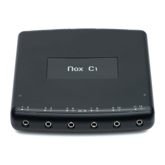
Nox C1 US Manual NOX C1 ACCESS POINT DESCRIPTION The Nox C1 is a Bluetooth® access point. It receives Bluetooth data stream from a Nox A1 Recorder, has input ports for receiving of signals originating from various auxiliary devices and internal sensors for ambient light measurement and pneumotachography. - Page 9 Nox C1 US Manual The figure below shows the front view of the Nox C1 Access Point, showing the six analog inputs, labelled DC IN 1-12. ~ 9 ~...
- Page 10 Nox C1 US Manual The figure below shows the rear of the Nox C1 Access Point, showing the six inputs available. Refer to the table below for input definition. The following table lists the Nox C1 Access Point inputs and the corresponding input labeling.
-
Page 11: Operating Nox C1 Access Point
Verify that the LED indicator light on top of the Nox C1 Access Point starts blinking amber immediately after connection of the power supply and starts blinking green when the startup sequence of the device is completed, and the Nox C1 Access Point is available for configuration. -
Page 12: Nox C1 Access Point Status
Nox C1 Access Point Status The Nox C1 Access Point has a built-in LED for device status indication. The LED is located on the top panel of the device. Refer to the table below for a description of the different states of the Nox C1 Access Point indicated with the LED. -
Page 13: Nox C1 Access Point Analog Inputs
The Sinbon C1 Extension cable (562012) can be used for extension purposes. The 12 analog channels offered by the Nox C1 Access Point have six inputs labeled DC IN from 1 to 12, see the figure above. The table below addresses the channel identification. -
Page 14: Nox C1 Access Point Differential Pressure Sensor
Nox C1 Access Point Differential Pressure Sensor To setup the Nox C1 Access Point for a recording of patient airflow at the proximal airway when using a PAP device, connect two Nox filter tube connectors to the differential pressure sensor inputs on the rear of the device, labelled + PRES -. -
Page 15: Nox C1 Access Point Serial Inputs
3.5 mm male stereo jack carrying the serial signal to a COM input (such as the Sinbon C1 Serial Cable (562013)) on the rear of the Nox C1 Access Point. The figure below shows the rear of the device, where the serial inputs are located. The serial inputs are labelled . -
Page 16: Nox C1 Access Point Ambient Light Sensor
Nox C1 US Manual Nox C1 Access Point Ambient Light Sensor The Nox C1 Access Point has a built-in ambient light sensor located on the top panel of the device; see the figure below (1). The light sensor can be used for light detection in the patient room. For the light sensor to work properly make sure not to cover the light sensor on the device. -
Page 17: Nox C1 Access Point Network Configuration
Nox C1 US Manual NOX C1 ACCESS POINT NETWORK CONFIGURATION Default Factory Configuration The factory state of the Nox C1 Access Point is listed in the table below. Nox C1 Network Configuration Details DHCP server DHCP pool: 192.168.101.64 - 192.168.101.127 Static IP address 192.168.101.10... -
Page 18: Nox C1 Access Point Setup
To ensure steady operation of the Nox Sleep System please follow the recommended system setup below. Use a separate local area network (LAN) for each Nox C1 Access Point and a computer running the Noxturnal US software, i.e. each patient room that includes the Nox C1 Access Point should be on a separate network. - Page 19 The Nox C1 Access Point is operated by the Noxturnal US software. For instructions on how to configure and operate the Nox C1 Access Point and Nox A1 Recorder from the Noxturnal US software refer to the Noxturnal US manual.
-
Page 20: Maintenance
To update the Nox C1 firmware you will need the Noxturnal US software running on a computer which is on the same network as the Nox C1 Access Point. Please refer to the Noxturnal US manual for more information on how to perform this task. - Page 21 Nox C1 US Manual Cleaning Warning: The Nox C1 Access Point device is not designed to give a specified degree of protection against harmful ingress of liquids. Do not autoclave or immerse the device in any kind of liquids. Ingress of liquids may result in electric shock.
- Page 22 United States of America. ** If any component damage occurs during cleaning process, contact Nox Medical immediately at support@noxmedical.com. Do not attempt to use the Nox C1 Access Point until the device has been inspected and repaired by authorized Nox Medical personnel.
-
Page 23: Compatible Devices, Sensors And Accessories
The following table includes information on accessories, sensors and devices that have been validated with the Nox C1 Access Point. The items listed below are Nox products and have been validated for use with the Nox C1 Access Point: NOX FILTER TUBE CONNECTORS... - Page 24 Radiometer TCM4/CombiM Radiometer TCM40/TCM TOSCA The 3 party FRIWO MP115 Medical-7555M/12 medical grade power supply has been validated with the Nox C1 Access point and is included in the C1 Kit. C1 Kit has the catalog number 544021 ~ 24 ~...
- Page 25 Nox C1 US Manual Nonin Respsense EtCO2 Monitor Resmed Airsense Resmed S9 Resmed Aircurve Masimo Radical-7 Tabletop Oximeter Nonin Model 7500 Tabletop Oximeter DIFFERENTIAL PRESSURE SENSOR Type Catalog Number Pneumoflow Sensor 552810 CLEANING Type Catalog Number PDI Sani-Cloth Plus Germicidal Disposable Cloth...
-
Page 26: Specifications
Nox C1 US Manual SPECIFICATIONS Nox C1 Access Point and Power Supply DESCRIPTION PROPERTIES FUNCTION Nox C1 Channels Ambient Light Channel Differential Pressure Channel Twelve Analog Input Channels (DC) Two USB Input Channels Two Serial Input Channels ... - Page 27 Nox C1 US Manual Nox C1 USB Inputs Number of Channels: 2 (currently nonfunctional) Number of Inputs: 2 USB 2.0 compliance High Speed (up to 480 Mbit/s) Connector: USB Type A Nox C1 Serial Inputs Number of Channels: 2 ...
- Page 28 Degree of protection against harmful ingress of liquids and particulate matter: The Nox C1 Access Point is classified IP20, i.e., as defined by the standard IEC 60529 it is protected against solid foreign objects of 12,5 mm diameter and greater, but it is not protected against harmful ingress of liquids.
- Page 29 Nox C1 US Manual Manufacturer information Date of manufacture Serial number Unique Device Identifier (UDI); the Application (01)15694311111498(11)YYMM Identifier (01) represents the device identifier (DI) DD(21)931XXXXXX (“15694311111498”), the Application Identifier (11) the production date/date of manufacture (“YYMMDD”, with “YY”...
- Page 30 Nox C1 US Manual Humidity limitation Atmospheric pressure limitation Unsafe for MR (Magnetic Resonance) Environment. Contains FCC ID: QOQBT111 Federal Communications Commission (FCC) ID label DC IN 1-12 Analog inputs (DC) Ethernet cable input ...
- Page 31 Frequency (RF) specifications for the Nox C1 Access Point. The Bluetooth® word mark and logos are registered trademarks owned by the Bluetooth SIG, Inc. and any use of such marks by Nox Medical is under license. Other trademarks and trade names are those of their respective owners.
- Page 32 Declarations of Conformity with the US Federal Communications Commission (FCC) The Nox C1 Access Point complies with Part 15 of the FCC Rules. Operation is subject to the following two conditions: 1. This device may not cause harmful interference, and 2.
- Page 33 Collateral Standard: Electromagnetic disturbances - Requirements and Tests. ELECTROMAGNETIC EMISSIONS The Nox C1 Access Point is intended for use in the electromagnetic environment specified below. The customer or the user of the device should assure that it is used in such an environment.
- Page 34 Nox C1 US Manual ELECTROMAGNETIC IMMUNITY The Nox C1 Access Point is intended for use in the electromagnetic environment specified below. The customer or the user of the device should assure that it is used in such an environment. Immunity test...
- Page 35 Nox C1 US Manual Refer to IMMUNITY TO Refer to IMMUNITY TO Proximity fields from RF wireless PROXIMITY FIELDS FROM RF PROXIMITY FIELDS FROM RF communications equipment WIRELESS COMMUNICATIONS WIRELESS COMMUNICATIONS IEC 61000-4-3 EQUIPMENT section EQUIPMENT section NOTE is the a.c. mains voltage prior to application of the test level.
- Page 36 IMMUNITY TO PROXIMITY FIELDS FROM RF WIRELESS COMMUNICATIONS EQUIPMENT The Nox C1 Access Point is intended for use in the electromagnetic environment specified below. The customer or the user of the device should assure that it is used in such an environment.
Need help?
Do you have a question about the Nox C1 and is the answer not in the manual?
Questions and answers