Table of Contents
Advertisement
Available languages
Available languages
Quick Links
Advertisement
Table of Contents

Summary of Contents for Altuna ERREBI DELTA ADVANCE
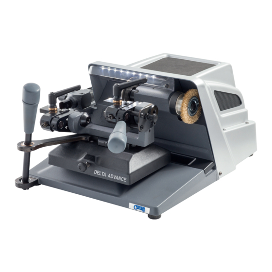
- Page 1 MACCHINA DUPLICATRICE DELTA ADVANCE MANUALE D´ ISTRUZIONE KEY CUTTING MACHINE DELTA ADVANCE INSTRUCTION MANUAL KOPIERMASCHINE DELTA ADVANCE ANWEISUNGSHANDBUCH MACHINE A TAILLER LES CLES DELTA ADVANCE NOTICE D’UTILISATION DELTA ADVANCE...
-
Page 3: Manuale D´ Istruzione
MACCHINA DUPLICATRICE DELTA ADVANCE MANUALE D´ ISTRUZIONE ITALIANO www.errebispa.com www.errebispa.com... -
Page 4: Caratteristiche Della Macchina
PRESENTAZIONE E ASPETTI GENERALI PREMESSA GENERALE TRASPORTO E IMBALLO TARGHETTA DI IDENTIFICAZIONE CARATTERISTICHE DELLA MACCHINA ACCESSORI CIRCUITO ELETTRICO DATI TECNICI TERMINOLOGIA DELLA CHIAVE PRINCIPALI ELEMENTI DELLA MACCHINA COMPONENTI E PARTI FUNZIONALI 2.6.1 Ganascia 2.6.2 Blocco della rotazione della ganascia destra 2.6.3 Fermo punta (modalità... - Page 5 PRESENTAZIONE E ASPETTI GENERALI 2.2 CIRCUITO ELETTRICO 1.1 ASPETTI GENERALI I componenti principali del circuito elettrico ed elettronico sono i seguenti: La macchina duplicatrice DELTA ADVANCE è stata progettata nel rispetto 1. Presa di corrente delle norme di sicurezza vigenti nella C.E.E. 2.
- Page 6 2.6 COMPONENTI E PARTI FUNZIONALI 2.6.1 GANASCIA La ganascia costituisce una parte fondamentale della macchina DELTA AD- VANCE. È stata studiata per poter duplicare il maggior numero possibile di chiavi, utilizzando i fermo punta di duplicazione di alcune di esse. 2.6.2 BLOCCO DELLA ROTAZIONE DELLA GANASCIA DESTRA La ganascia sul lato destro del carrello BIT dispone della levetta “16”...
-
Page 7: Regolazione Della Profondità Di Taglio
postazioni di serie. Tuttavia, qualora si verifichi una delle situazioni successi- • Serrare nuovamente la vite “M”. vamente descritte, è bene procedere alla realizzazione di alcune regolazioni: - Dopo la sostituzione di fresa, tastatore o ganascia. - Dopo un periodo d’uso prolungato. 3.1.1 REGOLAZIONE LATERALE •... - Page 8 3.2.1 CIFRATURA DELLE CHIAVI TIPO GORGES manda di lavorare realizzando delle pause, senza forzare la fresa. • L’arrotondamento si ottiene girando la leva “6” (muovendo la leva da- Agganciare la chiave nella ganascia. A seconda del tipo di chiave che si ll’alto verso il basso).
-
Page 9: Manutenzione
• • Estrarre il tastatore “T” usurato. • Agganciare la chiave vergine e la chiave da cifrare nelle corrispondenti • Installare il nuovo tastatore “T”. Accertandosi che la parte posteriore del ganasce utilizzando le leve “S”. tastatore appoggi contro il supporto “G”, serrare la vite “F”. •... -
Page 10: Sostituzione Dei Fusibili
di avanzamento, è necessario verificare lo stato dei fusibili. nualmente la cinghia mentre la si spinge sul laterale. Questa operazione va realizzata come segue: • Montare la cinghia nuova. Per farlo, orientare la macchina in modo che la parte posteriore resti di fronte a noi. In primo luogo, inserire la cinghia •... -
Page 11: Smaltimento Dei Rifiuti
possa lavorare comodamente. • Spegnere e scollegare la macchina. • Estrarre il carrello dalla macchina (BIT o TAGLI VERTICALI). SMALTIMENTO DEI RIFIUTI • Togliere il tappetino “K” della parte superiore. • Togliere il coperchio “N” che occulta il motore. Per farlo, togliere le 11 Per rifiuto si intende qualsiasi sostanza od oggetto derivante da attività... - Page 12 KEY CUTTING MACHINE DELTA ADVANCE INSTRUCTION MANUAL ENGLISH DELTA ADVANCE instruction manual...
-
Page 13: Presentation And General Aspects
PRESENTATION AND GENERAL ASPECTS 1.1 GENERAL ASPECTS 1.2 TRANSPORTATION AND PACKAGING 1.3 IDENTIFICATION LABEL MACHINE CHARACTERISTICS 2.1 ACCESSORIES 2.2 ELECTRIC CIRCUIT 2.3 TECHNICAL DETAILS 2.4 MAIN ELEMENTS OF THE MACHINE 2.5 COMPONENTS AND FUNCTIONAL PARTS 2.5.1 Changing the cutter and tracer 2.5.2 Cutter speed 2.5.3 Locking the slide on the “X”... -
Page 14: General Points
PRESENTATION AND GENERAL POINTS 2.3 TECHNICAL DATA Motor: Single phase 220V; 50Hz; 0,25Kw; 1,500 rpm (Optional: 110V; 60Hz; 0,25Kw; 1.1 GENERAL POINTS 1,500 rpm) Cutter: FP19 HSS (Ø80x1.4x16) Cutter speed: 750 rpm The DELTA ADVANCE cutting machine has been designed taking into account the Transmission: Ribbed belt. -
Page 15: Operation And Function
The probe spring facilitates the insertion of the probe between the teeth of the key, FINE POINT COUNTERPOINTS: for FEMALE keys with a small hole for the subsequent guidance of the key towards the cutter. Hole: from Ø3 to Ø4 Stem: greater than Ø5 2.6.6 LOCKAGE OF THE X AXIS THICK POINT COUNTERPOINT: for FEMALE keys with a large hole Hole: from Ø4 to Ø5.5... -
Page 16: Cutting Depth Adjustment
• In this position of the Lateral Stop “N2”, tighten the screw “R” to fix the Lateral Stop “N2”. • Move the inner bushing “C2”, until it touches the right-side of the Lateral Stop “N2”. • In this position of the internal bushing “C2”, lock it by means of the “Q” screw. •... -
Page 17: Replacing The Probe
• The bit of the key must stop against the lower part of the clamp. • The key bit must rest against the vertical wall of the clamp. • Start the rotation of the cutter, activating the corresponding switch. • With the lever “W”... - Page 18 • Turn off and unplug the machine. 4.3 BRUSH REPLACEMENT • Remove the “I” belt. This procedure is indicated in section 4.4 of this Manual. • Remove the lower protective plate “P”. To do this, release the 8 screws that To replace the brush, proceed as follows: hold it to the bench.
-
Page 19: Waste Disposal
• Unscrew the 2 wires of the “9” LED strip, from the connection strip. described, but in reverse order. • Take off the LED strip “9” from the support on which it is attached. • Remove the strip of LEDs “9”, so that their cables exit through the hole in the support. - Page 20 KOPIERMASCHINE DELTA ADVANCE ANWEISUNGSHANDBUCH DEUTSCH DELTA ADVANCE anweisungshandbuch...
-
Page 21: Wartung
EINFÜHRUNG UND HINTERGRUND 1.1 ÜBERSICHT 1.2 TRANSPORT UND VERPACKUNG 1.3 TYPENSCHILD MERKMALE DER MASCHINE ZUBEHÖR ELEKTRISCHER STROMKREIS TECHNISCHE DATEN SCHLÜSSELNOMENKLATUR HAUPTELEMENTE DER MASCHINE KOMPONENTEN UND FUNKTIONSTEILE 2.6.1 Spannbacken 2.6.2 Drehverriegelung der rechten Spannbacke 2.6.3 Reitstöcke (Verwendung) 2.6.4 Maximale Schlüssellänge 2.6.5 Tasterfederung 2.6.6 Verriegelung der X-Achse 2.6.7 Verriegelung der Y-Achse 2.6.8 Schlitten für vertikale Schnitte (optional) - Page 22 EINFÜHRUNG UND HINTERGRUND 1.1 ALLGEMEIN Die Kopiermaschine DELTA ADVANCE ist unter Berücksichtigung der in der EU geltenden Sicherheitsvorschriften konzipiert worden. Die Sicherheit des Personals im Umgang mit dieser Art von Maschinen kann nur durch ein gut gestaltetes Sicherheitsprogramm erreicht werden, einschließlich der Umsetzung eines Wartungsprogramms und Befolgung der Empfehlungen sowie der Einhaltung der in diesem Handbuch beschriebenen Sicherheitsstandards.
- Page 23 Schlüssel die höchstmögliche Anzahl an Schlüssel zu kopieren. manuelles Herausdrehen. 2.6.2 DREHVERRIEGELUNG DER RECHTEN SPANNBACKE 2.6.4 MAXIMALE SCHLÜSSELLÄNGE Die Spannbacke auf der rechten Seite des BIT-Schlittens verfügt über einen Knauf (16) zum Ver-/Entriegeln der Drehbewegung. Die Maschine DELTA ADVANCE ist ohne Einschränkungen in der Länge des zu kopierenden Schlüssels konzipiert.
-
Page 24: Einstellung Der Schnitttiefe
• In dieser Position die Schraube (R) festziehen, um den Seitenanschlag (N1) zu befestigen. • Einen langen Schlüssel ohne Dornloch in die rechte Spannbacke einspannen, sodass der Bart am Seitenanschlag (N1) anliegt. • X-Achse des Schlittens durch Betätigung des Knaufs (14) verriegeln. •... - Page 25 bewegt sich der Schlitten nicht). • Fräse durch Betätigen des entsprechenden Schalters einschalten. • Schlüssel an Fräse und Taster annähern. Es wird empfohlen, mit Bedacht vorzugehen, ohne die Fräse übermäßig zu belasten. • Während des Kopierens an der Schlüsselkopie entstehende Grate können mithilfe der Bürste entfernt werden.
- Page 26 4.1 AUSTAUSCH DER FRÄSE Der Austausch der Fräse erfolgt folgendermaßen: • Maschine ausschalten und Netzkabel trennen. • Zusammen mit dem Zubehör gelieferte Stange (A) in die Öffnung zur Verriegelung der Drehbewegung des Kopfes einführen. Dazu den Kopf mit der Hand bewegen. •...
-
Page 27: Austausch Der Sicherungen
4.6 AUSTAUSCH DER SICHERUNGEN Sollte die Maschine bei Betätigung des Betriebsschalters sich nicht einschalten, sind die Sicherungen zu überprüfen. Dieser Vorgang erfolgt folgendermaßen: 4.8 AUSTAUSCH DER ANSCHLUSSPLATTE • Maschine ausschalten und Netzkabel trennen. Der Austausch der Anschlussplatte erfolgt folgendermaßen: • Mithilfe eines kleinen Schraubendrehers den Sicherungshalter (U) vom Netzanschluss trennen. - Page 28 SICHERHEIT Zu Ihrer eigenen Sicherheit empfehlen wir Ihnen, diese Richtlinien zu befolgen: Versuchen Sie nicht, die Maschine zu starten oder zu bedienen, bis alle Sicherheitsfragen, Installationsanweisungen, Bedienungshinweise und Wartungsabläufe erfüllt und verstanden wurden. Trennen Sie immer das Netzteil, bevor Sie eine Reinigung oder Wartung durchführen.
-
Page 29: Notice D'utilisation
MACHINE A TAILLER LES CLES DELTA ADVANCE NOTICE D’UTILISATION FRANÇAIS www.errebispa.com... -
Page 30: Caracteristiques De La Machine
PRESENTATION ET ASPECTS GENERAUX GENERALITES TRANSPORT ET EMBALLAGE PLAQUE SIGNALÉTIQUE CARACTERISTIQUES DE LA MACHINE ACCESSOIRES CIRCUIT ELECTRIQUE INFORMATIONS TECHNIQUES NOMENCLATURE DE LA CLE PRINCIPAUX ELEMENTS DE LA MACHINE COMPOSANTS ET PARTIES FONCTIONNELLES 2.6.1 Etaux 2.6.2 Blocage de la rotation de l’étau côté droit 2.6.3 Contre-pointes (mode d’emploi) 2.6.4... - Page 31 PRÉSENTATION ET ASPECTS GÉNÉRAUX 5. Transformateur 6. LED d’éclairage 7. Plaques de connexion 1.1 GÉNÉRALITÉS La machine duplicatrice DELTA ADVANCE a été conçue conformément aux dispositions établies par les normes de sécurité en vigueur dans la CEE. La sécurité du personnel chargé d’utiliser ce type de machines n’est garantie qu’à travers un programme de sécurité...
- Page 32 2.6 COMPOSANTS ET PARTIES FONCTIONNELLES 3) RELÂCHER LES CLES : veillez à relâcher les clés avant de retirer les contre- pointes. 2.6.1 ETAUX L’étau s’avère être une pièce essentielle de la machine DELTA ADVANCE. Il a été 4) RETIRER LES CONTRE-POINTES : retirez les contre-pointes en les dévissant à conçu dans le but d’être en mesure de dupliquer le plus grand nombre possible de la main.
- Page 33 • Bloquez l’axe X du chariot au moyen de la manette « 14 ». • Réalisez une rainure droite d’environ 8 mm de profondeur. • Relâchez la clé de l’étau côté droit et fixez-la dans l’étau côté gauche. • Desserrez légèrement les deux vis « L » fixant le support du palpeur « 7 ». •...
- Page 34 veuillez les éliminer au moyen de la brosse. - Clé LONGUE FEMELLE (un/deux pannetons) : butée contre la butée latérale. Utilisez des contre-pointes pour femelle. 3.2.3 TAILLAGE DES COUPES VERTICALES • Remplacez le chariot BIT par le chariot de fixation pour COUPE VERTICALE. •...
-
Page 35: Remplacement De La Courroie
4.4 REMPLACEMENT DE LA COURROIE Assurez-vous que la fraise est installée avec les dents de coupe correctement orientées. Il convient de rappeler que la fraise tourne dans le sens horaire. La courroie de la machine DELTA ADVANCE est élastique ; par conséquent, aucun •... -
Page 36: Remplacement Des Fusibles
4.6 REMPLACEMENT DES FUSIBLES 4.8 REMPLACEMENT DE LA PLAQUE DE CONNEXION Si la machine ne se met pas en marche lorsque vous enclenchez les interrupteurs de mise en marche, veuillez vérifier l’état des fusibles. Pour remplacer la plaque de connexion, suivez les instructions suivantes : Pour ce faire, suivez les instructions suivantes : •... -
Page 37: Elimination Des Dechets
SECURITE Pour garantir votre sécurité, il est recommandé que vous observiez les recommandations suivantes : N’essayez jamais de mettre en marche ou de manipuler la machine sans avoir préalablement lu, bien compris et implémenté toutes les recommandations en matière de sécurité, les instructions d’installation, le guide d’utilisation et les procédures de maintenance. - Page 38 NT-36 DX-132 Carro BIT DX-140 DX-140 DX-139 NT-47 EC-215 NT-14 TI-107 PR-182 NT-32 III-2018 TI-107 NT-47 EC-215 M-VOL V:00 NT-33 DX-139 DX-185 TI-114 TI-114 NT-16 DX-140 NT-17 NT-35 DK-200 TI-96 NT-58 TI-161 TI-118 TI-99 DX-140 NT-40 EC-191 NT-34 TI-107 NT-41 DX-142 NT-54 DX-122...
- Page 39 EC-193 DK-207 Carro EC-195 EC-255 VOL RG PR-143 EC-198 III-2018 DK-198 NT-48 EC-206 V:00 NT-65 ECO-607 EC-207 EC-197 EC-207 EC-196 DK-197 DK-207 EC-198 DX-118 PR-143 EC-235 EC-14 NT-55 EC-214 DX-185 NT-56 EC-193 DK-207 TI-118 EC-195 EC-255 NT-54 DX-123 NT-67 NT-64 NT-37 PR-136 EC-77...
- Page 40 DELTA ADVANCE IV-2018 NT-18 NT-5 V:01 PR-156 NT-63 DX-98 TIN-43 EC-215 NT-13 DK-200 DX-72 TIN-45 NT-25 NT-8 EC-215 DX-87 EC-80 NT-26 DX-88 DX-140 DX-89 NT-1 DX-87 NT-9 EC-215 NT-6 EC-191 TI-72 EC-215 NT-24 DK-179 TIN-9 DKN-731 TI-73 FP-19 TIN-44 NT-73 DX-95 EC-249 DX-146...
- Page 41 YOUR KEY Errebi s.p.a. Unipersonale Errebi Deutschland GmbH Cibiana (BL) ITALY Velbert Germany Tel. 0435 542 500 Tel. (02053) 49 62-0 Fax. 0435 542 522 Fax. (02053) 49 62-22 www.errebispa.com www.errebi-gmbh.de info@errebispa.com info@errebi-gmbh.de Member of...
Need help?
Do you have a question about the ERREBI DELTA ADVANCE and is the answer not in the manual?
Questions and answers