Advertisement
Table of Contents
- 1 Table of Contents
- 2 Getting Started
- 3 Step 1: Unpacking
- 4 Step 1
- 5 Step 2
- 6 Step 3
- 7 Step 5: Tubing
- 8 Step 6: Wiring
- 9 Step 7: Power-Up
- 10 Basic Display and Keypad Operation
- 11 Password Operation
- 12 Verifying Functionality Using Diagnostic Alarms
- 13 Custom Set up
- 14 Diagnostic Functions
- 15 Specifications
- Download this manual
Advertisement
Table of Contents

Summary of Contents for Accutrol IAQ-Tek
- Page 1 IAQ-Tek Outdoor Airflow Transmitter Installation, Operation & Maintenance Manual Released Sept 2019 Accutrol, LLC 21 Commerce Dr. Danbury, CT 06810 Tel: 203-445-9991...
- Page 2 ARRANTY TATEMENT Accutrol LLC, having its principal place of business at 21 Commerce Dr. Danbury, CT USA ("Manufacturer") warrants its IAQ-TEK Outdoor Airflow Transmitter product (the "Products") as follows: 1. Limited Warranty. Manufacturer warrants that the Products sold hereunder will be free from defects in material and workmanship for a period of thirty-six (36) months from the date of purchase.
-
Page 3: Table Of Contents
Table of Contents Getting Started Step 1: Unpacking Step 2: Probe Installation Step 3: Transducer Installation Step 4: Monitor Installation Step 5: Tubing Step 6: Wiring Step 7: Power-Up Basic Display and Keypad Operation Password Operation Verifying Functionality Using Diagnostic Alarms Using Set-Up Wizards Custom Set Up Diagnostic Functions... -
Page 4: Getting Started
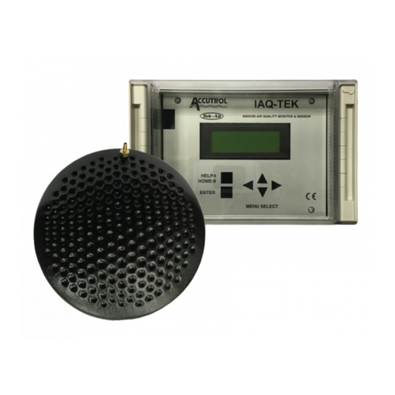
Getting Started Step 1 Unpacking Check that you have received the following items with your IAQ-TEK. (1) 50’ Cable Assembly (1) Monitor (1) Transducer PN 2001ASM00293 PN 44-0175 PN 1025CAB00030 Probe and Mounting Kit, Single Probe Kit Shown Below PN 2001ASM00320 10’... -
Page 5: Step 2
Getting Started Step 2 Probe Installation Install the probe(s) in the outdoor-air intake plenum per Figure 1 (Reference Appendix A for various types of installations). For multiple probe installations, determine probe location by dividing the damper area into as many quadrants as you have probes. -
Page 6: Step 3
Getting Started Step 3 Transducer Installation Mount the transducer vertically in the outdoor-air intake plenum in close proximity to the probe(s) per Figure 2. The transducer should be located no more that 4 feet from the probe. If it is not possible to mount the transducer into the outdoor-air intake plenum, it can be mounted outside and external to the air handler (provided it is in the shade) or in a machine room. -
Page 7: Step 5: Tubing
Getting Started Step 5 Tubing Installation Single Probe Configuration Measure the distance from the transducer “High” port to the probe Step 5a: “High” port. Step 5b: Cut a piece of the tubing provided to the proper length and attach it to “High”... -
Page 8: Step 6: Wiring
Getting Started Step 6 Wiring Transducer Wiring Connect the 50-foot cable assembly to the pressure transducer. One end of this cable has flying leads to allow cable to be run through conduit. Loosen the strain relief fitting nut on the lower right side of the monitor enclosure. Guide the cable end through the strain relief fitting and terminate the transducer wires to the monitor 9-pin terminal block per Figure 3. -
Page 9: Step 7: Power-Up
Step 7 Power-Up Activate the input power (24 VAC) to the Monitor. The IAQ-TEK Monitor Display should be at the HOME menu with ALARMS> NO. If Monitor Display indicates ALARMS> YES, you probably have an installation error. Refer to the Diagnostic Alarms Section for an explanation of the alarms. -
Page 10: Basic Display And Keypad Operation
Basic Display and Keypad Operation The IAQ-TEK display and keypad have been designed to function together in such a way as to provide a straightforward and intuitive tool for the setup, calibration, and troubleshooting of the monitor. Following is a brief description of the basic keypad operation. -
Page 11: Password Operation
The Diagnostic Alarms are used to provide diagnostic information on the performance of the product, and to alert the user to a possible malfunction. Following is a description of the Diagnostic Alarms that are available in the IAQ-TEK. Low Flow Alarm The Low Flow Alarm is used to alert the building operators that the intake volume has fallen below the minimum acceptable level. - Page 12 Verify Functionality Using Diagnostic Alarms Pressure Loss Alarm Should the incoming signal from the pressure transducer indicate a negative pressure, a Pressure Loss alarm flag will be initiated immediately and without delay. Outdoor Air Temperature Sensor Loss Alarm Should the OA Temp Input to the monitor go either high (input short) or low (input open), an OA Sensor Loss alarm flag will be initiated immediately and without delay.
- Page 13 The typical set-up of the IAQ-TEK is performed in three steps: 1. The Temperature Control Contractor sets up the monitor functions. 2. The Air Balancer verifies the system operation and calibrates the IAQ-TEK to field conditions. 3. The Facilities Manager sets the alarm limits to meet their requirements for minimum outdoor air.
- Page 14 Set-Up Using the Wizards Step 3: After answering all of the questions, the display should now read: TEMP CONTROL SETUP The ### should have > Confirm Outpt Scale the full scale CFM AO1 0 - ###### CFM value that you input. AO2 -40 120 degF Step 4:...
-
Page 15: Custom Set Up
Analog Out Flow FS -- Enter the full-scale range in CFM for the analog output scaling. Default is 20,000 CFM. Alarm Delay Period -- Several of the IAQ-TEK alarm conditions have their initiation inhibited for a delay period. This period is utilized to create a delay between the actual occurrence of an alarm and the reporting of the alarm either at the display, through the contact output, the digital outputs, or through communications. - Page 16 Custom Set-Up Press. Average Int -- Enter the Averaging Time in seconds between one and twenty seconds for the average pressure calculation. Factory default is 2 seconds. Use Fan Interlock? -- Select either NO (OFF) or YES (ON) to activate or deactivate the fan interlock.
-
Page 17: Diagnostic Functions
Diagnostic Functions The Diagnostic Functions provide the user with a method by which the functionality of the monitor system can be established by manually reading input status and manipulating outputs. Once activated, Diagnostic Functions will cause all calculation and alarming activities to halt. If left performing Diagnostic Functions for more that fifteen minutes, the monitor will exit Diagnostic Functions and return to normal operation and HOME. -
Page 18: Specifications
Specifications System Accuracy Intake Velocity 750 to 200 FPM; ± 5 % reading 200 to 100 FPM; ± 10% reading Probe and Transducer 6 7/8" 1/4" BARB FITTINGS IAQ- 1/4-20UNC I N DO O R A I R QUALITY M O N I T O R & SENSOR 3 1/2"... - Page 19 Monitor .165x.275 slot for #8 screws IAQ-Tek IND OOR AIR QU ALITY MONITOR & SEN SOR D anbury, C T 203- 791- 1400 3 1/8" HELP I HOME-II ENTER 9 3/8" MENU SELECT 3 1/8 8" Temperature Operating: 30 to 110 °F Storage: -40 to 150 °F...
- Page 20 Appendix A louver louver louver louver louver Damper Damper Damper AHU-3 AHU-3 AHU-3 Shared Plenum Rain Hood OA Damper OA Damper Air Handler Air Handler Mixing Plenum Mixing Plenum Cap Type Rain Hood Intake louver louver OA Damper OA Damper Before After Modification...
- Page 21 Appendix A louver louver McQuay Type Intake Standard Air Intake Rain Hood Rain Hood Air Handler Mixing Plenum Standard Rain Hood Intake...
Need help?
Do you have a question about the IAQ-Tek and is the answer not in the manual?
Questions and answers