Table of Contents
Advertisement
Quick Links
Advertisement
Table of Contents

Subscribe to Our Youtube Channel
Related Manuals for IBA ibaBM-eCAT

Summary of Contents for IBA ibaBM-eCAT
- Page 1 Bus monitor for EtherCAT® Manual Issue 1.15...
- Page 2 Any breach or infringement of this provision will result in liability for damages. ©iba AG 2020, All Rights Reserved The content of this publication has been checked for compliance with the described hard- ware and software. Nevertheless, deviations cannot be excluded completely so that the full compliance is not guaranteed.
-
Page 3: Table Of Contents
First Steps in ibaPDA .................. 18 Configuration as EtherCAT sniffer ............... 19 Configuration as EtherCAT slave ..............21 9.3.1 Integration into EtherCAT configuration ............21 9.3.2 Enabling in ibaPDA ..................24 Modules and tabs ..................25 9.4.1 Device module “ibaBM-eCAT” ..............25 Issue 1.15... - Page 4 Manual ibaBM-eCAT 9.4.2 „Standard“ module ..................30 9.4.3 „EtherCAT decoder“ module ................ 36 9.4.4 “Diagnostics” module .................. 38 9.4.5 „TwinCAT Request“ module ................. 40 Enhancement of data extraction ..............41 Technical Data ....................42 10.1 Main data ....................42 10.2 Dimension sheet ..................
-
Page 5: About This Manual
Manual About this manual This manual describes the construction, the use and the operation of the device ibaBM-eCAT. Target group This manual addresses in particular the qualified professionals who are familiar with han- dling electrical and electronic modules as well as communication and measurement tech- nology. -
Page 6: Used Symbols
Manual ibaBM-eCAT Used symbols If safety instructions or other notes are used in this manual, they mean: The non-observance of this safety information may result in an imminent risk of death or severe injury: By an electric shock! Due to the improper handling of software products which are coupled to input... -
Page 7: Introduction
Manual Introduction The device ibaBM-eCAT can be used for reading and recording of data transmitted over an EtherCAT ® bus with ibaPDA. For this purpose, the ibaBM-eCAT device is directly integrated into the bus after the EtherCAT master. Diagnostics and monitoring of the EtherCAT bus is also possible using the diagnostic signals integrated in the device and the EtherCAT browser. - Page 8 Manual ibaBM-eCAT A brief overview: Compact device for recording the communication of an EtherCAT bus Integration into the EtherCAT bus directly after the master, no additional adapters required Configuration as EtherCAT slave 2 EtherCAT interfaces (master and slave) ...
-
Page 9: Scope Of Delivery
The device is an electrical equipment. It may be used only in the following applications: Measurement data logging and analysis Applications of iba software products (ibaPDA, ibaAnalyzer etc.) The device may only be operated in conditions as specified in the technical data. -
Page 10: System Requirements
ibaFOB-2i-D / ibaFOB-2i-Dexp with extension module ibaFOB-4o-D ibaFOB-4i-D / ibaFOB-4i-Dexp with extension module ibaFOB-4o-D ibaFOB-io-ExpressCard (for notebooks) One ibaNet fiber optic patch cable (duplex) for connecting ibaBM-eCAT and ibaPDA-PC Software ibaPDA version 7.2.0 or later for measuring and recording data Firmware ... -
Page 11: Assembly And Disassembly
Manual Assembly and disassembly The device is provided with a mounting rail clip for installation. Assembly 1. Place the mounting rail clip attached to the device on the mounting rail. 2. Press the device down in such a way that the clip of the mounting rail engages with a click. -
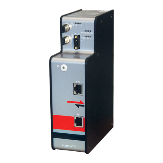
Page 12: Device Description
Manual ibaBM-eCAT Device description Views 1 Operating status indication L1…L4 2 Indication EtherCAT bus L30…L33 3 Indication device functions L34…L37 4 Connector power supply 24 V X14 5 Interface EtherCAT master X40 6 Interface EtherCAT slave X41 7 Rotary switch S1... -
Page 13: Operating And Indicating Elements
Manual Operating and indicating elements LED indicators with different colors show the operating status and the status of the EtherCAT channels. 7.2.1 Operating status Display Status Out of operation, no voltage supply (green/red) blinking green ready for operation on (red) device is booting;... -
Page 14: Rotary Switch S1
7.3.1 Power supply X14 The ibaBM-eCAT device requires an external 24 V DC (±10%) power supply (unregu- lated) and should be operated at a maximum of 0.7 A. The operating voltage should be run through the provided 2-pin Phoenix threaded coupling connector. If desired, you can order DIN rails or plug-in power supply units from iba. -
Page 15: Grounding Screw X29
Manual 7.3.4 Grounding screw X29 Proper connection of cable shielding to the device should be ensured. The shield con- nector (M6 screw) found on the bottom of the device should be connected with any total shield that serves for all sensor cables. Use a M6 cable lug for the connection. -
Page 16: System Integration
However, not all I/O data of the bus can be acquired. ibaBM-eCAT can only be operated at the bus end if it has been configured as an Ether- CAT slave and the option "Single/last device" has been enabled. -
Page 17: Integration As Single Ethercat Device
An existing EtherCAT bus is not changed here. However, in this configuration no I/O signals can be acquired from this EtherCAT bus without further modifications. All signals that are to be acquired via ibaBM-eCAT must be addressed directly in the controller as output signals to the device. ibaBM-eCAT must therefore be configured as an EtherCAT slave and integrated into the EtherCAT configuration. -
Page 18: Configuration With Ibapda
If a configuration has already been saved in the device, it is read out with the "Autode- tect" function. If there is no connection to the ibaBM-eCAT device at the time of configuration, it is possible to manually add the device module and the modules ("Add module") and pa- rameterize them. -
Page 19: Configuration As Ethercat Sniffer
ID is required, enter the UNC path, user name and password here. Exit this window with <Load symbols>. 4. Add a module “Standard“. Click on the link “ibaBM-eCAT” with the right mouse button and select “Add module” and the module “Standard”. - Page 20 Manual ibaBM-eCAT The following window will be opened: 2. In the tree structure, select the terminals whose signals should be recorded. Open the terminal symbol and select the signal. The signal is added to the appropriate signal table (analog or digital) by double clicking on the desired signal or clicking on the button <Add>.
-
Page 21: Configuration As Ethercat Slave
EtherCAT master. The signals are then configured and linked so that they are also avail- able for selection in the EtherCAT configuration file. The IO-Device file can be found on the DVD "iba Software & Manuals" in the directory "02_iba_Hardware\ibaBM-eCAT\01_IO-Device-File". - Page 22 Manual ibaBM-eCAT 5. The number of signals can be reduced channel by channel. The channel has to be disabled in the EtherCAT configuraton. In our example, disabling the PDO assignment 0x1600 deletes the Analog Channel 0. 6. You can also change the names of channels and signals:...
- Page 23 Manual 7. If another datatype is required for the analog signals than the preset one, it is possible to modify the datatype here. 8. Configure and link the signals as for the other slaves (please observe additional notes in the appendix, chapter 11.1): 9.
-
Page 24: Enabling In Ibapda
With the activation of the slave functionality the configuration field of the single or last EtherCAT device is displayed. If you want to operate ibaBM-eCAT with this type of integration (see chapter 8), also set this option to "True". 2. The signals previously exported from the EtherCAT master are now available in the "Standard"... -
Page 25: Modules And Tabs
9.4.1 Device module “ibaBM-eCAT” To operate ibaBM-eCAT with ibaPDA, the device must be set up in the I/O manager of ibaPDA. Please follow the instructions in chapter 9.1. The device module „ibaBM-eCAT“ has 5 different tabs. The “General”, “Diagnostics” and “EtherCAT browser”... - Page 26 (see chapter 9.2). If this option is not enabled (False) ibaBM-eCAT can work only in sniffer mode. Single/last device Only available with enabled EtherCAT slave. Enable this option (True), if you want to use ibaBM-eCAT as a single slave or as the last slave in an EtherCAT segment. Connection IP Address The IP address is determined by the slot number, the link number of the ibaFOB card and the device number the device is set to.
- Page 27 Write firmware Using this button you can install a firmware update. Select the update file „bm-ecat_xxx.iba“ in the browser and start the update with <OK>. Important note The update may take approx. 30 s and must not be interrupted. After an update the device will be automatically rebooted.
- Page 28 The following figure shows the detailed display of an EtherCAT telegram down to struc- ture or byte level. Figure 8: ibaBM-eCAT – “EtherCAT browser” tab, detailed display If no cyclic telegram traffic is detected, the following figure appears: Figure 9: ibaBM-eCAT – “EtherCAT browser” tab, no frames...
- Page 29 These tabs are only available after a module and signal configuration has been success- fully applied to ibaPDA. Figure 10: ibaBM-eCAT – “Analog” tab Figure 11: ibaBM-eCAT – “Digital” tab Both registers provide an overview of all acquired analog and digital signals with an online display of the currently acquired values (Actual).
-
Page 30: Standard" Module
Manual ibaBM-eCAT 9.4.2 „Standard“ module "Standard" modules can be added almost without limit. However, it has to be observed that each signal can be requested only once, i.e. not several times in several modules. By default, the comfortable signal selection is enabled via the symbol browser. If you do not want this or if no EtherCAT configuration file is available, you can enable access to the EtherCAT browser in the "General"... - Page 31 Manual Use symbol browser True: The signals can be selected via the symbol browser. Open the symbol browser with the “Select Browser” link at the bottom of this tab. False: The signals can be selected via the "EtherCAT browser" instead of the symbol browser.
- Page 32 Manual ibaBM-eCAT The EtherCAT symbol browser also offers a search function that makes it easier to select signals. Enter a search term in the “Search” tab and when clicking on the <Search> button all matching signals are listed. Figure 14: EtherCAT symbol browser If the EtherCAT configuration file contains comments for the signals, it is possible to search for comment terms as well.
- Page 33 Manual Figure 15: EtherCAT browser In the byte representation, select the initial value of the signal (offset) from the user data (green). Starting with this offset, 4 bytes are always highlighted in blue. The blue frame around the byte representation indicates whether you are in the input or output data with your selection.
- Page 34 Manual ibaBM-eCAT Figure 17: Add signal to signal list The subsequent signal with the same data type is automatically selected and can be immediately added to the same signal list (continuously) with <Add>. When all desired signals are selected, quit the EtherCAT browser with <Close>. If nec- essary, further signals can be added later at any time.
- Page 35 Manual Figure 20: Module “Standard” - “Analog” tab – signal selection via EtherCAT browser Figure 21: Module “Standard” – “Digital” tab – signal selection via EtherCAT browser Name When selecting signals via the symbol browser, the signal name is automatically im- ported.
-
Page 36: Ethercat Decoder" Module
Default If the option „Enable default values“ is enabled (true) in the "General" tab of the device module "ibaBM-eCAT" (see chapter 9.4.1.1), the additional column "Default" appears. Default values can be entered here, in case the EtherCAT connection is broken. - Page 37 Manual Basic settings, Advanced See chapter 9.4.2.1 Module Layout No. of decoders Configure the number of WORDs that can be decoded into digital signals. 9.4.3.2 “Digital” tab The signals are declared in two steps. First of all, the words you want to acquire as source for the digital signals have to be defined in sequential order.
-
Page 38: Diagnostics" Module
Only the activated digital signals are considered when counting the number of licensed signals, hence no additional signal for the source word. ibaBM-eCAT only acquires one analog value, which is then decoded by ibaPDA. Thus, the range of analog values is used in ibaBM-eCAT for acquiring large amounts of digital signals. 9.4.4 “Diagnostics”... - Page 39 Manual 9.4.4.1 “General” tab Figure 25: Module “Diagnostics” – “General” tab Basic settings See chapter 9.4.1.1. "Update signals" link The "Update signals" link is used to read the list of diagnostic signals from the device, for example if you want to load or reset the list.
-
Page 40: Twincat Request" Module
Manual ibaBM-eCAT Figure 26: Module “Diagnostics” – “Analog” tab Figure 27: Module “Diagnostics” – “Digital” tab For an explanation of the columns, see chapter 9.4.2.4. 9.4.5 „TwinCAT Request“ module The description for the "TwinCAT Request" module can be found in the ibaPDA supple- mentary manual for the request function for TwinCAT. -
Page 41: Enhancement Of Data Extraction
Manual Enhancement of data extraction The signals or data selected in ibaPDA are extracted from the data stream of the Ether- CAT bus for acquisition in the device. The data should be extracted as efficiently as possible so that large amounts of data can be recorded even with small bus cycles. -
Page 42: Technical Data
Manual ibaBM-eCAT Technical Data 10.1 Main data Short description Designation ibaBM-eCAT Description Bus monitor for EtherCAT buses Order number 13.127000 Bus interfaces (EtherCAT) Number 2 (1x master, 1x slave) for 1 EtherCAT bus Data recording Sniffer without additional bus configuration... - Page 43 Manual Connector type 2 ST connectors (62.5 µm/125 µm) for RX and TX, cable length up to 2000 m without repeater Supply, operating and indicating elements Power supply 24 V DC (±10 %), not stabilized Power consumption Max. 8 W...
-
Page 44: Dimension Sheet
Manual ibaBM-eCAT 10.2 Dimension sheet Figure 28: Dimension sheet (dimensions in mm) Figure 29: Dimension sheet device with cables (dimensions in mm) Issue 1.15... -
Page 45: Appendix
11.1 IO Device File (ESI) < Version 1.7 When using ESI files up to version 1.5 for ibaBM-eCAT the following limitation occurs with the TwinCAT version v2.11.1555 (System Manager Version v2.11.0): When the ESI file of ibaBM-eCAT is integrated in the EtherCAT configuration a conflict occurs with the EtherCAT configuration in ... -
Page 46: Ftp Connection To The Device
\02_iba_Hardware\ibaBM-eCAT\02_USB-Driver\ 3. After having installed successfully, an additional network connection is available with the device name „IBA AG USB Remote NDIS Network Device“. 4. A fixed IP address must be assigned to this interface. The address has to be from this range: 192.168.0.n with n = 2…254 and the subnetmask 255.255.255.0. -
Page 47: Signal List File
Manual 6. The following files are displayed in the file window: 11.2.3 Signal list file The signal list file contains the FO configuration and the signal mapping including the signal names from the ibaPDA configuration. The following figure shows an example of a signal list file: Figure 31: Signal list example Issue 1.15... -
Page 48: Ethercat Browser Overview
The column “Fiber optic Signal” (blue frame in the following figure) shows the corre- sponding allocation on the fiber optic cable for each signal. This may be used for the connectivity to ibaLogic or other iba-hardware. Figure 32: Signal mapping in the fiber optic cable The given address with the corresponding offset, shown in the cloumn „PDA setting... -
Page 49: Support And Contact
Mailing address iba AG Postbox 1828 D-90708 Fuerth Germany Delivery address iba AG Gebhardtstrasse 10 DE-90762 Fuerth Germany Regional and Worldwide For contact data of your regional iba office or representative please refer to our web site www.iba-ag.com. Issue 1.15...
Need help?
Do you have a question about the ibaBM-eCAT and is the answer not in the manual?
Questions and answers