
Summary of Contents for BE Ag & Industrial BE-SBS G Series
- Page 1 BE-SBSxxG Snowblower Manual Operations & Parts Manual For Models: • BE-SBS50G • BE-SBS76G • BE-SBS60G • BE-SBS7680G • BE-SBS72G Purchase Date Model No. Serial No. Dealer...
-
Page 2: Safety Precautions
BE-SBSxxG SAFETY PRECAUTIONS 1. Be sure all exposed moving parts such as shafts and adapters are properly guarded and that all coupling devices are securely attached before applying power. Do not use unless all shields are in place. 2. Do not wear loose fitting clothing in the vicinity of any moving parts. 3. -
Page 3: Safety Decals
BE-SBSxxG SAFETY DECALS Colour: Red DANGER Colour: Yellow CAUTION Location: Blower Side Location: Blower Back Stones or other objects Do not service, adjust or Lower or block elevated components before may be thrown great servicing or when leaving the machine. repair any equipment Elevated components can fail and cause distances by the auger,... -
Page 4: Operation
BE-SBSxxG SET UP 1. Turn hood to point directly behind blower (PTO side). 2. Lift hood assembly o and spread a light coat of grease on outside of blower mainframe pipe. 3. Replace hood assembly. 4. Install hood turner as per instructions. 5. -
Page 5: Installation
BE-SBSxxG INSTALLATION A proper initial installation will give you years of satisfactory service on your equipment. Please read carefully following instructions which have been specially made to help you and make you satisfied with your purchase. WARNING! Unfortunately, snowblowers will be faced with forgotten or hidden objects under the snow, such as chain, tires, stones, pieces of wood, etc. - Page 6 BE-SBSxxG INSTALLATION (CONT.) Previous examples clearly demonstrate that universal joint angle is directly related with life of PTO in order to reduce angle, it is necessary to increase the distance between snowblower and tractor. It is impossible to increase the distance between snowblower and tractor, in order to maintain a reasonable angle at PTO, it is recommended to use a large size of PTO, That is a greater capacity PTO, (please refer to your dealer for more details).
-
Page 7: Setup Instructions
BE-SBSxxG SET UP INSTRUCTIONS 1. Un-crate items and compare with the parts breakdown found in the Operator’s Manual. 2. Bolt on left and right skid shoes according to Image 1. 3. Assemble the chute. Following manner of assembly in Image 2 and Image 3. Refer to the snowblower diagram in the diagram in the operator’s manual for exploded view. - Page 8 BE-SBSxxG SET UP INSTRUCTIONS (CONT.) 4. Assemble hitch, see Image 6. 5. Assemble the hitch top assembly and chute crank support brackets as shown in image 7. 6. Refer to page 2 of the operator’s manual for final service and installation of snowblower. Note: Hand crank support bracket must be installed on the bottom of chute flange.
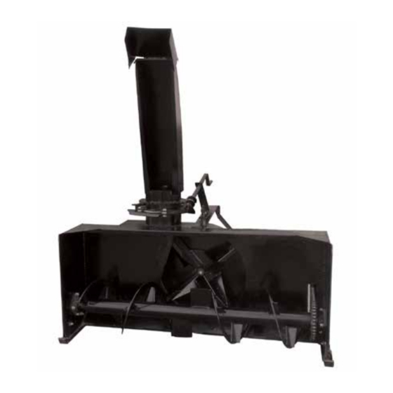
- Page 9 BE-SBSxxG SNOWBLOWER DIAGRAM...
-
Page 10: Snowblower Parts List
BE-SBSxxG SNOWBLOWER PARTS LIST REF NO. PART NO. DESCRIPTION REF NO. PART NO. DESCRIPTION 130001 Main Frame 130033 Nylon Washer 130002 Lock Nut M10 130034 Special Washer ø12x0.2 130003 130035 Bearing SAPF-206-20 C/W Flange Bearing 6301-2RS1 130004 Nut M6 130036 Lock Nut M8 130005 Bolt M10x20... -
Page 11: Shield Assembly
BE-SBSxxG SHIELD ASSEMBLY Plastic Shield Assembly #69.888.998 Tractor Yoke # 21-10-00 Shearbolt Clutch Series 4 # 57-117-18 Complete PTO - Bondioli Type Series 4 # 69.888.400 Nut # 09-000.008 Nyloc M8x1.25 Shearbolt # 01.008.045 M8 x 45x1.25 (GR8.8) - Page 12 BE-SBSxxG AVOIDABLE DAMAGES POSSIBLE CAUSES CORRECTIVE ACTIONS SHIELD - Excessive wear of shield - Insu cient lubrication - Follow lubrication instructions bearings. - Incorrect chain mounting. - Mount chain to allow maximum angularity. - Shield interfering with - Avoid contact of the shields implement.
- Page 13 BE-SBSxxG AVOIDABLE DAMAGES POSSIBLE CAUSES CORRECTIVE ACTIONS Cross Kit - Cross arms broken. - Extreme torque peak or chock - Use appropriate safety device. load. - Change to a larger P.T.O. size. - Axial Loads too high. - Shorten P.T.O. shaft - Replace defective cross bearings.
- Page 14 BE-SBSxxG AVOIDABLE DAMAGES POSSIBLE CAUSES CORRECTIVE ACTIONS Quick-disconnect yoke - Quick-disconnect pin tight or - Quick-disconnect pin dirty - Clean, oil and follow service completely seized. (insu cient maintenance). instructions. - Quick-disconnect pin damaged - Quick-disconnect pin defective - Replace quick-disconnect pin. (broken or bent).
Need help?
Do you have a question about the BE-SBS G Series and is the answer not in the manual?
Questions and answers