Table of Contents
Advertisement
Quick Links
Advertisement
Table of Contents

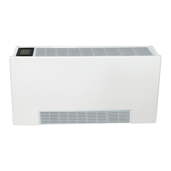
Summary of Contents for MDL Solutions PFWSL-01
- Page 1 SK2017 AHRI PFWSL-V/P-AECM-001...
- Page 2 Page 1 of 53 INVESTING IN QUALITY, RELIABILITY & PERFORMANCE ISO 9001 QUALITY World Leading Design and Technology Every product is manufactured to meet Equipped with the latest air-conditioning test rooms the stringent requirements of the and manufacturing technology, we produce over internationally recognized ISO 9001 50,000 fan coil units each year, all conforming to the standard for quality assurance in design,...
-
Page 3: Table Of Contents
Page 2 of 53 Table of Contents A. Technical Data ..................................5 A.1. General Description ................................5 A.2. General Specification ................................6 A.2.1. 2-Pipe Systems ................................6 A.2.2. 4-Pipe Systems ................................7 A.3. Coil Data ....................................8 A.3.1. 2-Pipe Systems ................................8 A.3.2. - Page 4 Page 3 of 53 E. Networking System ................................34 E.1. Master-Slave Network ............................... 34 E.1.1. Master Unit Control Settings ............................34 E.1.2. Master-Slave Network Setup ............................35 E.1.3. Master-Slave Communication Method ........................37 E.2. Open Modbus protocol ..............................38 F. Control Specifications: Flexible Function PCB – W Type Control ..................41 F.1.
- Page 5 Page 4 of 53 Model Code Nomenclature PFWSL AECM AECM EC Motor Configuration Complete function onboard PCB with integrated group control functionality. Flexible function onboard PCB with zone control functionality. Chilled/Hot Water, 4-Pipe Chilled/Hot Water, 2-Pipe Chilled Water, 2-Pipe with Electric Heater Unit Sizes.
-
Page 6: Technical Data
Page 5 of 53 A. Technical Data A.1. General Description The product represents all-in-one solution for cooling, heating and dehumidification. It achieves high energy saving levels as it can be combined with low-temperature heat generators such as heat pump, condensing boilers and solar collectors. With its sophisticated temperature regulator, it guarantees thermal comfort in every season. -
Page 7: General Specification
Page 6 of 53 A.2. General Specification 2-Pipe Systems Product range: PFWSL-Y-ECM Super Slim Universal Fan Coil with EC Motor PFWSL-Y-V~-ECM Super Slim Universal Unit 2-pipe with EC Motor PFWSL-[Size]-Y-V~-AECM Configuration 2-pipe Number Of Fan Blowers Power Supply (V/Ph/Hz) 115/1/60 Unit Configuration ~S: Complete function onboard PCB with integrated group control functionality. -
Page 8: 4-Pipe Systems
Page 7 of 53 4-Pipe Systems Product range: PFWSL-Y-P~-ECM Super Slim Universal Unit 4-pipe with EC Motor PFWSL-Y-P~-ECM Super Slim Universal Unit 4-pipe with EC Motor PFWSL-[Size]-Y-P~-AECM Configuration 4-pipe Number Of Fan Blowers Power Supply (V/Ph/Hz) 115/1/60 Unit Configuration ~S: Complete function onboard PCB with integrated group control Operation Control functionality. -
Page 9: Coil Data
Page 8 of 53 A.3. Coil Data 2-Pipe Systems Fins per No. of No. of Model Fin height Fin Length Fin width Tube Ø Inch Rows Circuits PFWSL-01 11-7/8 PFWSL-02 19-3/4 PFWSL-03 11-13/16 27-5/8 15.0 1-3/4 PFWSL-04 35-1/2 PFWSL-05 43-3/8 4-Pipe Systems... -
Page 10: Dimensions
Page 9 of 53 A.4. Dimensions MODEL PFWSL-01 PFWSL-02 PFWSL-03 PFWSL-04 PFWSL-05 29 1/8 44 7/8 52 3/4 60 5/8 22 13/16 22 13/16 22 13/16 22 13/16 22 13/16 5 1/8 5 1/8 5 1/8 5 1/8 5 1/8 (All dimensions are approximate within 1/16 of an inch of those indicated.) -
Page 11: Valve Information (Optional)
Page 10 of 53 A.5. Valve Information (Optional) 2-Way 3/4” Valve Body Valve Body Dimensions (mm) Valve Code (valve body + ON/ OFF thermoelectric actuator) SGS14HFCA-23010101 2-3/16 1-7/8 2-1/2 (G3/4”) 3-Way 3/4” Valve Body Valve Body Dimensions (mm) Valve Code (valve body + ON/ OFF thermoelectric actuator) SGS14HFCA-23010102... - Page 12 Page 11 of 53 2-Way 1/2" Valve Body Valve Body Dimensions (mm) Valve Code (valve body + ON/ OFF thermoelectric actuator) SGS14HFCA-23020101 2-1/16 1-7/8 2-1/2 (G1/2”) (All dimensions are approximate within 1/16 of an inch of those indicated) Differential Pressure Chart for 1/2" Valve Cv [US gpm, psi] SK2017 AHRI PFWSL-V/P-AECM-001...
-
Page 13: Installation
Page 12 of 53 B. Installation B.1. Safety Precautions • When installing, performing maintenance or servicing Polar Air fan coil units observe the precautions stated in this manual as well as those stated on the labels attached to the unit. •... -
Page 14: Installation And Location
Page 13 of 53 B.2. Installation and Location The unit location should be established by the installation designer, services engineer or by a technically competent person before installation. It should take into account the technical requirements as well as the relevant current laws and regulations. -
Page 15: Front Panel Removal
Page 14 of 53 B.3. Front Panel Removal Step 1: Unlock grill and remove the filter. Step 2: Lift the front panel and remove it. B.4. Electrical Connection The fan coil comes fully wired and only requires connecting to the mains electricity supply and to any room controls. Remove the front panel, then control box is shown below. -
Page 16: Piping Connections
Page 15 of 53 B.5. Piping Connections The fan coils have been designed and made for installation in heating and air-conditioning systems. The characteristics of the water fittings are given below: Main pipes connection The position of the water fittings may be reversed from left to right during installation. Installation diagram of water connections 1. -
Page 17: Valve And External Drain Pan Installation
Page 16 of 53 B.6. Valve and External Drain Pan Installation Horizontal type Piping for 2-Pipe System Water Outlet 3/4” Water Inlet 3/4” 3-Way 4 Port Valve 3/4” Horizontal Drain Pan Piping for 4-Pipe System 2-Way Valve 1/2” for Heating Coil 2-Way Valve 1/2”... - Page 18 Page 17 of 53 Vertical type Piping for 2-Pipe System 3-Way 4 Port Valve 3/4” Water Outlet 3/4” Water Inlet 3/4” Vertical Drain Pan Piping for 4-Pipe System Chilled Water Outlet 1/2” 2-Way valve 1/2” for Cooling Coil Hot Water Outlet 1/2” 2-Way Valve 1/2”...
-
Page 19: Maintenance
Page 18 of 53 C. Maintenance C.1. General Maintenance 1. Installation and maintenance should be performed by qualified personnel who are familiar with local codes and regulations, and are experienced with this type of appliance. 2. Confirm the unit has been switched OFF before installing or service. 3. -
Page 20: Fan Motor Assembly Maintenance
Page 19 of 53 C.4. Fan Motor Assembly Maintenance Step 1: Remove the front panel. Step 2: Loosen screws on the mounting brackets. EC motor can be removed. Step 3: Once finished with maintenance, remount the front panel. SK2017 AHRI PFWSL-V/P-AECM-001... -
Page 21: Control Specifications: Complete Function Pcb - S Type Control
Page 20 of 53 Control Specifications: Complete Function PCB – S Type Control Abbreviations Ts = Setting temperature AUX1 = Hot water free contact Tr = Room air temperature AUX2 = Chilled water free contact Ti1 = Chilled water coil temperature MTV1 = Chilled water valve Ti2 = Hot water coil temperature MTV2 = Hot water valve... -
Page 22: Wiring Diagrams
Page 21 of 53 D.2. Wiring Diagrams Standard S Type Control PCB SK2017 AHRI PFWSL-V/P-AECM-001... -
Page 23: Master-Slave Networking Wiring Diagram
Page 22 of 53 Master-Slave Networking Wiring Diagram Master Unit Slave Unit Connect to other slave units SK2017 AHRI PFWSL-V/P-AECM-001... -
Page 24: Configuration Settings
Page 23 of 53 D.3. Configuration Settings DIPA-S1 DIPB-S2 SW1-SW5 Network address SW5/SW6 Fan Qty setting setting SW5=0 Single fan application SW6=1 SW5= Twin fans application Master / Slave setting SW6=1 SW6=1 Master SW6=0 Slave Preheat temperature setting SW4=1 82.4 SW4=0 96.8 SW7/SW8 Operating mode... - Page 25 Page 24 of 53 Fan Coil Unit ON/OFF There are 3 ways to turn the system on or off: a) By the ON/OFF button on the remote handset or wired wall pad; b) By the programmable timer on the handset or wired wall pad. c) By the manual control button on fan coil unit.
-
Page 26: Control Logics For 2-Pipe System
Page 25 of 53 D.4. Control Logics for 2-Pipe System With Valve Configuration COOL MODE MTV2, AUX1 and electric heater are always off. If Tr ≥ Ts+1.8ºF (or +7.2 ºF if economy contact is activated), cool operation is activated, MTV1 and AUX2 are turned on. Indoor fan runs at set speed. - Page 27 Page 26 of 53 PRE-HEAT Pre-heat without electrical heater If Ti1 < 97ºF [or < 82ºF is selected by DIPB-S2 position SW4], MTV1 and AUX1 are on, indoor fan runs at 200rpm. If Ti1 ≥ 100 ºF [or ≥ 86ºF is selected by DIPB-S2 position SW4], MTV1 and AUX1 are on, indoor fan runs at set speed. If indoor coil temperature sensor is damaged, pre-heat time is set for 2 minutes and indoor fan runs at set speed.
-
Page 28: Without Valve Configuration
Page 27 of 53 Without Valve Configuration COOL MODE a) Electric heater, AUX1, MTV1 and MTV2 are always off. b) If Tr ≥ Ts+1.8 ºF (or +7.2ºF if economy contact is activated), cool operation is activated, AUX2 is on. Indoor fan runs at set speed. -
Page 29: Control Logics For 4-Pipe System
Page 28 of 53 D.5. Control Logics For 4-Pipe System Note: 4-pipe system must always be equipped with 2 valves. COOL MODE a) MTV2, AUX1 and Electrical Heater always off. b) If Tr ≥ Ts+1.8 ºF (or +7.2 ºF if economy contact is activated), cool operation is activated, MTV1 and AUX2 are turned on. Indoor fan runs at set speed. - Page 30 Page 29 of 53 POST HEAT Without Electrical Heater a) If Ti2 ≥ 100 ºF, when MTV2 and AUX 1 are off, indoor fan continues to run at set speed. b) If 97 F ≤ Ti2 ≤ 100 F, when MTV2and AUX1 are off. Indoor fan keeps original state. If Ti2 <...
-
Page 31: Sleep Mode
Page 30 of 53 D.6. Sleep Mode a) The sleep mode can only be set when the unit is in cool mode or heat mode. b) If the sleep mode is activated when the unit is in cool mode, then the indoor fan will run at low speed and Ts will increase by 3.6ºF over 2 hours. -
Page 32: Modulating Valve Control Under Energy Saving Mode
Page 31 of 53 D.8. Modulating Valve Control Under Energy Saving Mode If the modulating valve is used, the water flow is adjusted from 0 to 100% according to the room temperature and set temperature. The controller adjusts the modulating valve signal input from 0 to 10VDC by PID calculation every 10 seconds. D.9. -
Page 33: Led Display And Error Description
Page 32 of 53 D.13. LED Display and Error Description LED receiver in ABS housing with 19-11/16” (SGS14HFCA-01010101) or 70-7/8” (SGS14HFCA-01010102) pre-wiring Complete Function PCB – S Type Control Fan speed setting LED display Condition High speed Red LED On Normal Medium speed Yellow LED On... -
Page 34: Led Display On Master/Slave Connection
Page 33 of 53 D.14. LED Display on Master/Slave Connection The error message indicating the defect status of all slave units will be shown in LED lights on the master unit. Master unit LED Unit No. Blink Remedy Unit 2 failure RED LED blinks 2 times, stops for 3s Check unit 2 communication plug and fix it Unit 3 failure... -
Page 35: Networking System
Page 34 of 53 E. Networking System E.1. Master-Slave Network The control PCB can be set either as a master unit or slave unit. Mater Unit Function a) The master unit sends data regarding its setting to the slave unit. b) The master unit settings are unit ON/OFF, Mode, Fan Speed, Timer, Clock, Set Temperature, Louver Function, and Sleep Function for handset operation. -
Page 36: Master-Slave Network Setup
Page 35 of 53 Master-Slave Network Setup 1) Disconnect the communication plug from the control box 2) Communication plug A, B, A, B is printed on the main PCB. When you connect the wires, please ensure connection of A to A and B to B. 3) Connection wire i. - Page 37 Page 36 of 53 First unit Middle unit Last unit iii. Wire connection check a) After the wire connection is completed, please check that the wire colours correspond. b) Check the wire contact by using a multimeter. contact contact contact contact contact contact...
-
Page 38: Master-Slave Communication Method
Page 37 of 53 Master-Slave Communication Method There are two modes for the master-slave structure. Global Control communication The master unit will broadcast the settings to all slave units. During normal operation, slave units can receive commands from its wireless handset and wall pad control panel. Upon receiving the master global commands, all slave unit settings will be replaced by the master settings. -
Page 39: Open Modbus Protocol
Page 38 of 53 E.2. Open Modbus protocol Transfer Mode: RTU, BAUD Rate: 9600bps, 8 data bit, 1 stop bit, None parity bit The communications require a delay of 80ms between reading an answer and sending the next command. All temperatures are equal to reading data*10 accuracy: 0.1 degree F. - Page 40 Page 39 of 53 Holding Register table: Description Address Type* Remark Cooling mode = 01(H) Humidify mode = 02(H) Mode setting 300000 Fan mode = 04(H) Heating mode = 08(H) Auto mode = 10(H) Low speed = 04(H) Medium speed = 02(H) Fan speed setting 300001 High speed = 01(H)
- Page 41 Page 40 of 53 Input Register table: Description Address Type* Remark Dip switch 1 status 400000 Dip switch 2 status 400001 Room temperature sensor 400002 Ti1 temperature sensor 400003 Ti2 temperature sensor 400004 Bit0 = Room temperature sensor error Bit1 = Ti1 temperature sensor error Bit2 = Ti2 temperature sensor error Bit3 = Float switch error Bit4 = Indoor coil low temperature protection...
-
Page 42: Control Specifications: Flexible Function Pcb - W Type Control
Page 41 of 53 F. Control Specifications: Flexible Function PCB – W Type Control F.1. Features a) Integrated fan relays for zone control applications. b) ON/OFF thermostat input and low-voltage modulating fan speed input flexibility. Simple error diagnostic and LED error display. F.2. -
Page 43: Wiring Diagrams
Page 42 of 53 F.4. Wiring Diagrams Standard W Type Control PCB SK2017 AHRI PFWSL-V/P-AECM-001... -
Page 44: Zone Control Wiring Diagram (On/Off Thermostat)
Page 43 of 53 Zone Control Wiring Diagram (On/Off Thermostat) WIRING DIAGRAM WIRING DIAGRAM 0~5VDC / 0~5VDC / 0~5VDC / 0~10VDC(S3 closed) 0~10VDC(S3 closed) 0~10VDC(S3 closed) Auto speed signal Auto speed signal Auto speed signal 230V~50HZ 230V~50HZ 230V~50HZ YL/GR YL/GR YL/GR X-DIS X-DIS... -
Page 45: Control Logics Specification
Page 44 of 53 F.5. Control Logics Specification Unit Power On/Off a) The unit is turned ON when any of the fan speed inputs (H/M/L) are ON, OR Auto ON/OFF signal input is ON. b) The unit is turned OFF only if all of the fan speed inputs (H/M/L) are OFF AND Auto ON/OFF signal input is OFF. Alarm Protection and Error Display a) If the float switch is open for 5 minutes, then the (NC) voltage-free alarm contact shall be open and the (NO) voltage free alarm contact shall be closed. -
Page 46: User Interface
Page 45 of 53 G. User Interface G.1. Remote Handset for S Type Control Interchange F and C on Display Press up and down buttons for 3 seconds, then release. Louver It is not available. Swing It is not available. Attention When unit with handset is the master unit, its settings are automatically sent to the slave units;... -
Page 47: Wired Wall Pad Controller For S Type Control
Page 46 of 53 G.2. Wired Wall Pad Controller for S Type Control Features: Communication with remote handset. On/Off button to turn unit On or Off. Fan speed can be set Hi, Medium, Low and Auto. Mode button to set the unit cooling, heating, fan or dehumidify. -
Page 48: Thermostat For W Type Control
Page 47 of 53 G.3. Thermostat for W Type Control This thermostat adopts digital control technology with large LCD display. It shows the following items: working states (cool, heat or ventilation), the speed of fan coil, room temperature, set-point. There are following keys on the panel: On/Off “... -
Page 49: Remote Handset For Thermostat In W Type Control
Page 48 of 53 PARAMETER SETTING: Parameter A: When thermostat is closed, press“ ” and “” buttons simultaneously and hold for 3 seconds. The thermostat will display “00 or 01”,use “△” or “▽” key to adjust。 Press “ ” to enter next parameter setting, Press “△” or “▽” key to adjust。 Repeat the second step above to set other parameter. -
Page 50: Sensor Resistance R-T Conversion Table
Page 49 of 53 H. Sensor Resistance R-T Conversion Table Resistance : R (77°F) = 10KΩ ± 1% Beta Constant : B (25/85) = 3977 ± 1% Rmin Rnom Rmax Rmin Rnom Rmax (°F) (KΩ) (KΩ) (KΩ) (°F) (KΩ) (KΩ) (KΩ) 182.7 191.8... - Page 51 Page 50 of 53 Resistance : R (77°F) = 10KΩ ± 1% Beta Constant : B (25/85) = 3977 ± 1% Rmin Rnom Rmax Rmin Rnom Rmax (°F) (KΩ) (KΩ) (KΩ) (°F) (KΩ) (KΩ) (KΩ) 100.4 5.614 5.759 5.907 1.417 1.474 1.532 102.2...
-
Page 52: Troubleshooting
Page 51 of 53 I. Troubleshooting Symptoms Cause Remedy The fan coil does not - Check for presence of voltage No voltage start up - Check fuse on board Mains switch in the “OFF position - Place in the “ON” position Faulty room control - Check the room control - Check fan motor... -
Page 53: Accessories Descriptions
Page 52 of 53 J. Accessories Descriptions J.1. Electrical Heater Electric Heater module is supplied for winter heating as an alternative to the auxiliary hot water coil. Electric Heater is installed in the same way and same position as the Auxiliary 1 row heating coil for 4-pipe system. Note: Airflow should not drop below the values for minimum speed. -
Page 54: Auxiliary External Drain Pan
Page 53 of 53 J.2. Auxiliary External Drain Pan DPANPS-UNSL-RH is a painted steel drain pan for suspended ceiling installation or built-in horizontal installation with right- sided coil connections. DPANPS-UNSL-LH is a painted steel drain pan for suspended ceiling installation or built-in horizontal installation with left-sided coil connections. - Page 55 Page 72 of 72 MDL Solutions 2275 Upper Middle Rd E Oakville, ON L6H0C3 general@mdlsoln.com SK2016 PFWBC-V/P-ECM-001 289 799-3414 | www.mdlsoln.com...
Need help?
Do you have a question about the PFWSL-01 and is the answer not in the manual?
Questions and answers