Table of Contents
Advertisement
Quick Links
Thank you for choosing our product
Cheyenne Livestock & Products Inc.
PO Box 25
Brush Prairie, WA 98606
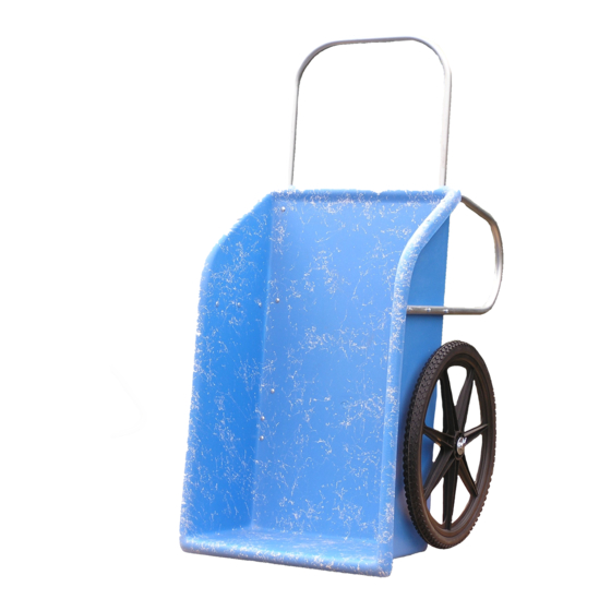
STEP BY STEP INSTRUCTIONS FOR THE "COLT-26" OR "WORKHORSE "HAND CART
NOTE:
ALL BOLTS SHOULD BE PLACED WITH THE SLOTTED HEAD ON THE INSIDE OF THE CART.
HARDWARE PACKAGE: Please find and check the hardware package. See the pictorial inventory of the assembly hardware
on the back of these instructions.
TOOLS REQUIRED (not included): A flat blade screwdriver and a 7/16th end wrench or an adjustable jaw wrench.
1. LEG 1: Turn the cart body (PART A) on its side. Match the numbers on one of the legs (PART G) to the number on
the cart. Use (5) of the 1 ½ inch long bolts (PART J) and (5) self-locking nuts (PART H) to attach the leg to the cart
body
2. AXEL BRACKETS: With the cart remaining on its side, use the (8) 1 ¼ inch long bolts (PART K) and (8) self-locking
nuts to attach both axel brackets (PART D) to the bottom of the cart. IMPORTANT! Do not tighten the bolts for
the axel brackets more than finger tight.
3. LEG 2: Turn the cart body on its other side. Match the numbers on one of the legs (PART G) to the number on
the cart. Use (5) 1 ½ inch long bolts (PART J) and (5) self-locking nuts (PART H) to attach the leg to the cart body.
4. AXEL: Turn the cart body upside down. Slide the axel (PART C) through both axel brackets. Be sure that the same
amount of axel protrudes beyond the sides of the cart on both sides (about 3 – 3/8 inch) to allow for the wheels.
5. WHEELS: Put one collar (PART E) on each end of the axel, then the wheels (PART B), followed by another collar.
Now tighten the set screws of the collar. See drawing 1. Tighten the bolts that hold the axel brackets to the
cart body.
6. HANDLES: With the cart remaining upside down. Match the numbers on the handle (PART F) to the number on
the cart body. Install the handle on the outside of the cart body using the last (6) 2-inch-long bolts (PART I) and
(6) self-locking nuts (PART H). Install the head of the bolts on the inside of the cart.
The diagram below shows the cart in an upside-down position.
COLT-26 OR WORKHORSE
Telephone: (360) 574-7771 or 1-800-424-7575
Fax: (360) 574-0490
Advertisement
Table of Contents

Related Manuals for Cheyenne WORKHORSE

Summary of Contents for Cheyenne WORKHORSE
- Page 1 Telephone: (360) 574-7771 or 1-800-424-7575 Brush Prairie, WA 98606 Fax: (360) 574-0490 STEP BY STEP INSTRUCTIONS FOR THE “COLT-26” OR “WORKHORSE “HAND CART NOTE: ALL BOLTS SHOULD BE PLACED WITH THE SLOTTED HEAD ON THE INSIDE OF THE CART. HARDWARE PACKAGE: Please find and check the hardware package. See the pictorial inventory of the assembly hardware on the back of these instructions.
- Page 2 PARTS LIST WHEELS (2) PART “B” TUB (1) AXEL (1) PART “A” PART “C” HANDLE (1) AXEL COLLARS (4) AXEL CLIPS (2) PART “F” PART “E” PART “D” LEGS (2) 1/4” NUTS (24) PART “G” PART “H” DRAWING 1 2” BOLTS (6) PART “I”...
Need help?
Do you have a question about the WORKHORSE and is the answer not in the manual?
Questions and answers