Table of Contents
Advertisement
Quick Links
AS USED BY LEADING ROADSIDE RECOVERY OPERATIONS - THIS PRODUCT IS
INTENDED SOLELY FOR USE OF BONA FIDE MOTOR TRADERS / TYRE FITTING BAYS
TO ASSIST THEIR CUSTOMERS WHEN THE ORIGINAL SECURITY KEY HAS BEEN LOST
BLADES A & B WILL BE DAMAGED
IF USED ON HARDENED NUTS
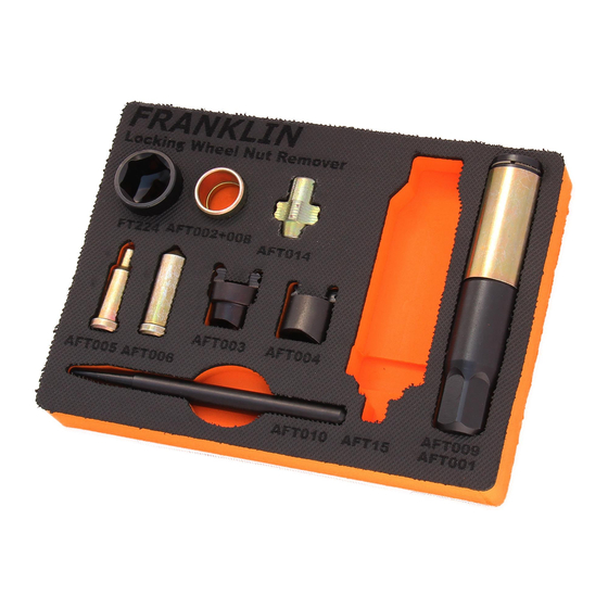
AFT25 WHEEL NUT TOOL WITH BLADES A B C
AFT26 WHEEL NUT TOOL WITH BLADES A B C
& AFT15 HEAVY DUTY IMPACT DRIVER
Locking
Remover Guide
ALWAYS WEAR SAFETY GEAR WHEN
USING TOOLS & EQUIPMENT
Wheel Nut
BLADE C IS REQUIRED
2
4
6
8
10
12
14
14
15
16
FOR THIS TYPE OF
HARDENED NUT
Advertisement
Table of Contents

Summary of Contents for Franklin AFT25
-
Page 1: Table Of Contents
AFT25 WHEEL NUT TOOL WITH BLADES A B C AFT26 WHEEL NUT TOOL WITH BLADES A B C & AFT15 HEAVY DUTY IMPACT DRIVER Locking Wheel Nut Remover Guide ALWAYS WEAR SAFETY GEAR WHEN USING TOOLS & EQUIPMENT AS USED BY LEADING ROADSIDE RECOVERY OPERATIONS - THIS PRODUCT IS... -
Page 2: Blade A And Wheel Nut Selection
Blade and Mandrel Inner Shroud Required Apply tape to Tool Outer Shroud, see page 15. BLADES A & B WILL NO Inner BE DAMAGED IF USED Shroud ON HARDENED NUTS Required BLADE C IS REQUIRED FOR THIS TYPE OF HARDENED NUT... - Page 3 Note Ordinary nut but with rounded corners Special Tip Cut through lock with ordinary chisel inside the outer shroud before using blade A Use centre punch in Ensure tool on centre centre for mandrel using c/punch and mandrel...
-
Page 4: Blade B And Wheel Nut Selection
Blade and Mandrel Ensure tool on centre using the centre punch first then mandrel Centre punch the nut when no hole is present Apply tape to Tool Outer Shroud, see page 15. Line blade with Blade B fits tight holes over top of nut BLADE C IS REQUIRED FOR THIS TYPE OF... - Page 5 Note Test hardness with Line blade tips with centre punch holes where possible Line blade with holes Large 4 x 4 nut...
-
Page 6: Blade C And Wheel Nut Selection
Disposable Blade BLADE C IS REQUIRED FOR THIS TYPE OF HARDENED NUT Blade C is designed to remove two sizes of locknuts. Choose the end that best locates into the locknut pattern. One end of the blade is designed to remove all four locknuts on one vehicle. 1) Offer Blade C to the locknut. - Page 7 Fig: 1 Fig: 2 The end that best locates in the centre Once the correct end is determined, piece of the locknut should be used. insert the Blade C into the tool body and re-fit the Outer Shroud. Fig: 4 A typical example of a “moulded”...
-
Page 8: Jaguar / Range Rover Key
Jaguar / Range Rover Key (Optional extra available from Dynomec) (AFT020 & AFT030 optional extras available - see page 16) Instructions For Use. Remove the Outer Shroud from the Tool Body of the Locking Wheel Nut Remover Kit. Slide the Short Outer Shroud over the Tool Body. Clip the Jaguar Key (or Range Rover Key) into the Tool Body. - Page 9 JAGUAR KEY (Including short outer shroud and mandrel) RANGE ROVER KEY (Including short outer shroud and mandrel) PLEASE NOTE: Use with Impact Driver ONLY WARNING THESE BLADES WILL BE EASILY DAMAGED IF NOT USED AS RECOMMENDED WITH THE AFT15 HEAVY DUTY IMPACT DRIVER...
-
Page 10: Assembly
Assembly Separate Outer Shroud from Tool Body OUTER SHROUD TOOL BODY Select the correct Blade to suit locknut/stud. See pages 2-9 When using Blade A if the inner shroud will fit over Locknut place onto Blade as below – this will help keep tool on centre. - Page 11 Ensure the Spring is inside the Tool Body – Clip Blade Assembly into Tool Body via the Spring Ring. Refit the Outer Shroud over the Blade and onto the Tool Body (the Outer Shroud should protrude approximately 5mm ahead of the tips of the Blade in order to shield the locknut/stud and thereby reducing the risk of damage to the wheel itself i.e.
-
Page 12: Instructions For Use
Instructions For Use WARNING Blades A or B must not be used on hardened nuts or studs. Using the centre punch provided test the locknut to be removed for hardness. If the centre punch makes a pop mark without deforming, proceed as per instructions. - Page 13 Keep contact between the blade and the locknut. The 24mm impact socket is now required. Now use one of the following Now use one of the following methods methods of removal: (see Page 14) of removal : Good Quality Air Impact Wrench Dynomec Impact Driver AFT15 Heavy Duty Impact Driver ** supplied.
-
Page 14: Using An Impact Driver
USING AN IMPACT DRIVER push in & twist Using the Impact Driver in the approved manner, ensure the Blade is still located into the ‘grooves’ – apply inward and anticlockwise-rotation pressure to the Impact Driver before each strike with a 3lb club hammer. Only use the one directional high torque impact driver supplied with the Locking Wheel Nut Remover Kit. -
Page 15: Hints & Tips
Hints & Tips To keep the tool central, apply tape to the Outer Shroud to make the tool a good fit into the hole in the wheel. This is especially useful when using Blades A & B. If all other attempts have been unsuccessful and the locknut is over-tight, support the tool with a jack...
Need help?
Do you have a question about the AFT25 and is the answer not in the manual?
Questions and answers