
Subscribe to Our Youtube Channel
Related Manuals for Vante 4600

Summary of Contents for Vante 4600
- Page 1 INSTRUCTION MANUAL MODEL 4600 RF Tube Sealer Power Source Doc. No. 46000810-01 Rev. D...
- Page 2 This page intentionally left blank.
- Page 3 Vante ® 3480 E. Britannia Dr., Suite 120 Tucson, AZ 85706 USA Telephone (520) 881-6555 (520) 323-9055 Toll Free (877) 565-5557 Part No. 46000810-01 Rev. D ® 9/12 Vante...
- Page 4 This page intentionally left blank...
-
Page 5: Intended Audience
Application The Model 4600 RF Power Source is a part of a system and cannot be used independently. When used in conjunction with Model 4605 & 4105 sealings heads it is the Power Source used to make seals on tubing made of RF-reactive thermoplastic materials typically used in biopharmaceutical manufacturing. -
Page 6: Proprietary Information
Proprietary Information All rights are reserved. Copying of the protected designs associated with the Model 4600 Power Source is strictly prohibited without the prior written consent of Vante. User Alerts Throughout this document WARNINGS, CAUTIONS and NOTES are employed to notify the user of important and/or critical information. -
Page 7: Regulatory Compliance Information
Low Voltage Directive – 73/23/EEC (as amended by 93/66/EEC) Conformity Assessment Body: TUV SUD America. For inquires related to the CE marking of this product, please contact Vante at 3480 E. Britannia Dr., Suite 120 Tucson, Arizona 85706 U.S.A. +1-520-881-6555, +1-520-323-... - Page 8 This page intentionally left blank viii...
-
Page 9: Table Of Contents
Table of Contents Preliminary Information..................v Document Scope .....................v Intended Audience ..................v Application ......................v Exclusions and Limits of Liability ..............v Proprietary Information ................vi User Alerts ....................vi Safety Symbols ..................... vi Regulatory Compliance Information ............vii Table of Contents ..................ix Table of Figures ....................x Table of Tables ..................... -
Page 10: Table Of Figures
Table of Figures Figure 1.1 RF Tube Sealer with Hand Held and Bench Top Sealing Heads ..1 Figure 1.2 Model 4600 RF Tube Sealer Components ..........2 Figure 1.3 RF Power Source Power Interface Panel..........4 Figure 1.4 Serial Plate and Fuse/Rating Labels for Power Source ......4 Figure 2.1 RF Power Cable Attachment (For Use with a Model 4105) ....7... -
Page 11: Table Of Tables
Table of Tables Table 1.1 Tube Sealer Component Functions ............3 Table 1.2 Tubing Specifications ................5 Table 3.1 Troubleshooting Guide .................16... -
Page 13: Power Source Description
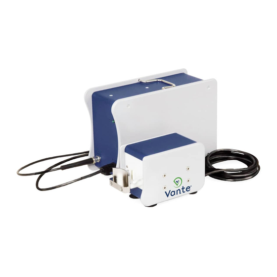
1. Power Source Description 1.1 Product Overview The Vante Model 4600 RF Tube Sealer is a compact, portable device which employs radio frequency (RF) to make uniform, quality seals on a variety of tubing sizes without power adjustment by the user. The System consists of the Model 4600 Power Source (“the Power Source”) and can be teamed with either the Model 4105 hand-held,... -
Page 14: Component Identification
Source requires no manual power or timing adjustment by the user. 1.3 Component Identification The Model 4600 Power Source, when coupled with the various sealing heads, becomes a system. Figure 1.2 shows the component parts of the sealing system with a Hand Held Sealing Head and a Bench Top Sealing Head. - Page 15 ® Vante Model 4600 Component Function Model 4600 RF Power Provides RF power to the sealing head. Automatically controls RF power and Source sealing time. RF Ready Light LED located on the front of the unit labeled "READY". Illuminates when RF power is ready.
-
Page 16: Figure 1.3 Rf Power Source Power Interface Panel
® Vante Model 4600 RF Ready Light Serial Tag RF Power Power Switch Output Fuse Holder Power Input Receptacle DC Output Figure 1.3 RF Power Source Power Interface Panel US.PAT NOS 280515, 4488028, 4496819, 4529859, 5349166 Figure 1.4 Serial Plate and Fuse/Rating Labels for Power Source CAUTION: Unit is equipped with dual fuses. -
Page 17: Operating Environment
1.5 Tubing Specifications Table 1.2 illustrates typical tubing sizes found in the biopharmaceutical industry. The table also represents those tubing sizes validated at Vante. It is not intended to absolutely define operating performance characteristics. Allowances are made for dimensions and tolerances that fall outside of these typical tubing sizes. -
Page 18: Seal Cycle
® Vante Model 4600 1.6 Seal Cycle The Sealer “seal cycle” (or duty cycle) is defined as the time period, in seconds, between consecutive, repetitive seals. The maximum seal cycle and hourly rate will vary with different types and sizes of tubing, processing media and environmental conditions of the facility. -
Page 19: Power Source Operation
2.1 Setup Remove the components from their protective shipping containers and visually inspect them for obvious damage. Contact an authorized Vante service center if any damage is found. If possible, retain shipping containers and packing materials for future use. Connect the AC power cord to the power input receptacle located on the rear of the Power Source. -
Page 20: Sealing Procedure With Model 4105 Hand Held Sealing Head
® Vante Model 4600 connector clockwise to lock it in place. Plug the seven-pin connector into the DC output. See Figure 2.2. BNC Connector Seven Pin Connector Figure 2.2 Model 4605 Bench Top Sealing Head Cable Attachment CAUTION: Do NOT attempt to use any other length or type of RF power cable. -
Page 21: Figure 2.4 Incorrect Technique For Holding The Sealing Head
® Vante Model 4600 CAUTION: The sealing region must open facing upward so the operator may ensure that the tubing is fully seated between the RF jaw and ground jaw and clearly observe the sealing indicator lamp on the sealing head. -
Page 22: Figure 2.6 Releasing The Sealing Head Lever At Seal Completion
® Vante Model 4600 WARNING: Dimming of the indicator light will occur, but do not release the lever until after the indicator light is completely off! Premature lever release will cause incomplete sealing and/or ruptured tubing. Holding the lever closed will not cause overheating or burn-through of the tubing. -
Page 23: Sealing Procedure With Model 4605 Bench Top Sealing Head
® Vante Model 4600 WARNING: If you observe arcing while making a seal, follow the instructions in the Troubleshooting Guide section under “Arcing or Bad Seals.” Although a seal made when you experience arcing may look acceptable, it may be inadequate. Take precautions as if this is an inadequate seal. -
Page 24: Figure 2.8 Incorrect Sealing Method
® Vante Model 4600 WARNING: Always operate the Sealing Head with the splash guard in place. Do NOT pull the tubing through the sealing region. Under no circumstances should the tubing be pulled at the instant of sealing. This may cause an opening in the tubing, which will subject the media to non-sterile conditions and the user to potentially hazardous fluids. -
Page 25: Figure 2.9 Repeating The Seal Process
® Vante Model 4600 Completed seal Lift tubing off seal trigger PUSH tubing to next seal position Figure 2.9 Repeating the Seal Process WARNING: Be sure to push the tubing through the sealing region to the next position. Under no circumstances should the tubing be separated by pulling it at the instant of sealing. -
Page 26: Seal Spacing
® Vante Model 4600 2.4 Seal Spacing The Sealer is designed to allow repetitive seals to be made on a length of tubing filled with media. However, several factors control how closely the seals may be spaced. Seals which progress along an open-ended length of tubing may be spaced as desired, but ½... -
Page 27: Maintenance
® Vante Model 4600 3. Maintenance Other than periodic cleaning, or when moisture, media, or other contaminants are visible, the sealing head and Power Source are designed to be maintenance free and to withstand substantial wear and tear. Damage may occur as a result of dropping either the Sealing Head or the Power Source. -
Page 28: Troubleshooting
® Vante Model 4600 3.2 Troubleshooting The following chart offers diagnosis and actions for many commonly-reported problems. For any problems or failures not listed, please contact the Vante Customer Service Department. Problem Diagnosis Action Not sealing. No power to Power Ensure all connections are correct (refer Source. -
Page 29: Failure Isolation
If the Power Source performs properly, then the sealing head is suspected. If the Power Source fails to function properly, then the Power Source may be the cause of malfunction. ™ ™ In any event, contact your nearest Vante authorized service representative or Vante evaluation and repair. 4.2 Fuse Replacement If the unit is plugged into an AC Power Source, and the RF Ready light is not illuminated "|"... -
Page 30: Repair
Do not attempt a field repair of any kind. Questions regarding repairs should be directed to an authorized Vante service center. To return the Power Source to Vante for repair, call for a Return Material Authorization (RMA) number with the unit serial numbers available. - Page 31 CAUTION: Failure to properly package the components for shipping may increase any repair costs. NOTE: Units returned to Vante for repair are subject to biohazard charges if any Sealer component is contaminated with media or other potentially biohazardous materials.
- Page 32 ® Vante Model 4600 This page intentionally left blank...
-
Page 33: Radio Frequency System Safety Considerations
5.2 RF Effects On Human Tissue Misuse or direct contact between tissue and RF electrode(s) can result in severe RF burns. 5.3 RF Effects On Pacemakers There is no evidence that Vante RF instruments interfere with the function of modern cardiac pacemakers. 5.4 Electrical Safety...
Need help?
Do you have a question about the 4600 and is the answer not in the manual?
Questions and answers