
Related Manuals for NuWave SSRMAN-1BFS Series

Summary of Contents for NuWave SSRMAN-1BFS Series
- Page 1 Rev.1.5 06/18 SSRMAN-1BFS S ERIES SERS ANUAL YNCHRONOUS URST IRING ODULE 2013 OPYRIGHT ECHNOLOGIES...
-
Page 2: Table Of Contents
SSRMAN-1BFS Users Manual Page 2 TABLE OF CONTENTS Ordering Codes ..............................2 Description ................................. 2 Features ..............................3 Installation / Safety Information ......................... 3 Solid State Relay Installation ........................3 Mounting Instructions ..........................4 Electrical Connections ..........................4 3.3.1 Internal Diagram ..........................4 Limited Warranty ............................ -
Page 3: Features
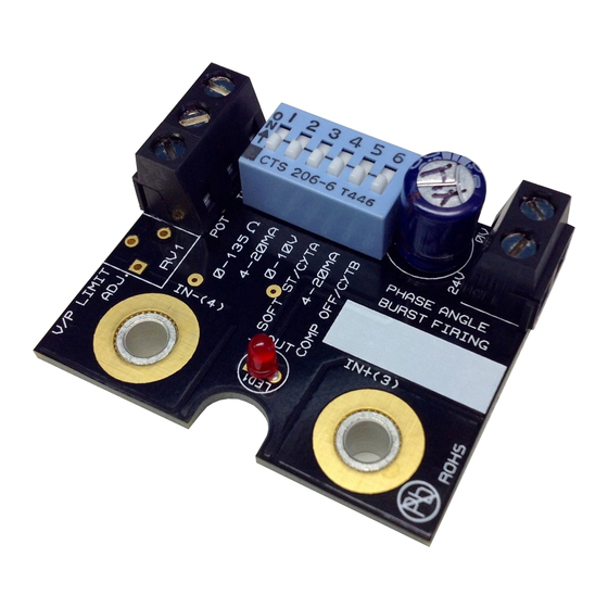
SSRMAN-1BFS Users Manual Page 3 2.1 Features • Command input accepts 4-20mA, 0-10V, 0-5V, 0-135 , Potentiometer • Fast Sychronous Burst Algorithm provides true linear power at fast cycle times • Drives multiple solid state relays (SSRs) • Small (1.75x1.40”) module mounts on the input terminals of an inexpensive SSR •... -
Page 4: Mounting Instructions
SSRMAN-1BFS Users Manual Page 4 3.2 Mounting Instructions The SSRMAN mounts directly to the control input terminals of an SSR using two #6-32 screws. Some relays have short input screws and longer screws will required to reach through the contacts on the SSRMAN. Be sure to observe the correct polarity when mounting the module (module should be positioned over the SSR). -
Page 5: Operation
SSRMAN-1BFS Users Manual Page 5 NuWave Technologies, Inc. warrant this product to be free from defect in workmanship and materials for a period of two (2) years from the date of purchase. 1. Should unit malfunction, return it to the factory. - Page 6 SSRMAN-1BFS Users Manual Page 6 The SSRMAN-1BFS has 4 available cycle times settable via the dipswitches. The cycle times are specified below in # of cycles and can be correlated to their respective times using the table below for both 50 and 60 Hz Line frequencies (note that the –LVC option only has the fast burst firing cycle time and the dipswitch is disabled): Cycle Cycle...
-
Page 7: Cycle Times - 266Ms Selection (Fast Synchronous Burst Firing)
SSRMAN-1BFS Users Manual Page 7 *Synchronous Firing Method When burst firing AC with conventional PWM, there is a tradeoff between resolution and cycle time. Generally the cycle time should be chosen based on the mass of the load to be controlled; the larger the load mass, the longer the cycle time can be. For the best possible resolution, its standard practice to choose the longest cycle time that can be used without causing process ripple. -
Page 8: Fast Synchronous Burst Firing Advantages
1 6 : 4 0 : 0 0 h : m i n : s NuWave Fast Synchronous Burst algorithm results in excellent linearity / resolution (above) 4.6 Line Voltage Compensation (-LVC Option) The SSRMAN-1BFS’ line voltage compensation keeps the power constant on the load as the line voltage changes. -
Page 9: Power Limit
SSRMAN-1BFS Users Manual Page 9 With a 10% drop in line voltage, SSR MA N load power drops less than 2% (120V, 1KW, 14.4 O hm Load ) Withou t Line Voltage Compensation SSR MA N -1BFS Line Voltage Compensation 120VAC 120VAC 108VAC... -
Page 10: Control Output
SSRMAN-1BFS Users Manual Page 10 Command Input 0-5V (Default) Potentiometer 0-10V 4-20mA 1-5V 2-10V 0-135* *Module must be ordered as SSRMAN-1BFS-135 for 0-135 input support. 4.9 Control Output The SSRMAN-1BFS SSR output drive is a DC pulsed current limited drive signal of 10V/15mA (24VAC power). -
Page 11: Three Phase Operation
SSRMAN-1BFS Users Manual Page 11 The SSRMAN-1BFS’ RED output LED will turn on when the output is on. The output LED is wired in series with the SSR’s input. If there is a poor connection on the SSR input terminals or a problem with the SSR’s input, the output LED will not become energized. -
Page 12: Electrical Specifications
65mA (Power consumption 1.6W MAX). Line Frequency Range 47-63 Hz. Terminal Block wire Gauge 16-30 AWG Terminal Block Material Polyamide 6.6 UL 94 V-0, Black 6. Mechanical Dimensions 1.75" Max Height is 0.6” 7. Contact Information NuWave Technologies, Inc 866-379-3597 www.nuwaveproducts.com Copyright 2013 ECHNOLOGIES... -
Page 13: Wiring Diagram (4-20Ma, 0-5V, 0-10V Inputs)
SSRMAN-1BFS Users Manual Page 13 8. WIRING DIAGRAM (4-20mA, 0-5V, 0-10V Inputs) SSRMAN-1BFS WIRING DIAGRAM (4-20mA, 0-5V, 0-10V INPUT) AC POWER HEATER SOURCE FUSE PROCESS CONTROLLER 4-20mA, 0-5V,OR 0-10V FUSE 24VAC CONTROL TRANSFORMER 9. WIRING DIAGRAM (Potentiometer Input) SSRMAN-1BFS WIRING DIAGRAM (POTENTIOMETER INPUT) AC POWER HEATER SOURCE... -
Page 14: Wiring Diagram (0-135 Ohm Input)
SSRMAN-1BFS Users Manual Page 14 10. WIRING DIAGRAM (0-135 Ohm Input) SSRMAN-1BFS WIRING DIAGRAM (0-135 Ohm) AC POWER HEATER SOURCE FUSE 0-135R FUSE 24VAC CONTROL TRANSFORMER 11. WIRING DIAGRAM 3 PHASE DELTA – Zero Crossing SSRMAN-1BFS WIRING DIAGRAM 3 PHASE INSIDE DELTA CONNECTION FUSE 24VAC COMMAND INPUTS:... -
Page 15: Wiring Diagram 3 Phase 4 Wire Y - Zero Crossing
SSRMAN-1BFS Users Manual Page 15 12. WIRING DIAGRAM 3 PHASE 4 WIRE Y – Zero Crossing SSRMAN-1BFS WIRING DIAGRAM 3 PHASE 4 WIRE Y CONNECTION FUSE 24VAC CONTROL TRANSFORMER FUSE FUSE 24VAC CONTROL TRANSFORMER FUSE HEATERS 0-10V FUSE COMMAND 24VAC CONTROL TRANSFORMER FUSE...
Need help?
Do you have a question about the SSRMAN-1BFS Series and is the answer not in the manual?
Questions and answers