
Summary of Contents for Drum HYDRAPAK
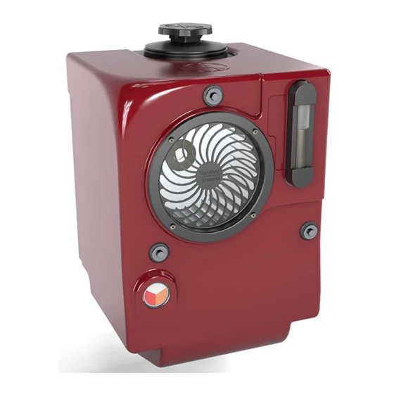
- Page 1 Installation, Operating & Maintenance Manual (Original Instructions) HYDRAPAK OIL COOLER 4991015005 February 2018...
-
Page 2: Table Of Contents
Relief Valve Setting Procedure ........13 Maintenance Instructions Schedule ................14 Removing the Outer Cover ........... 15 Changing the Filter Element ......... 16 Fault Finding ..............17-18 Spare Parts Diagrams ..........19-22 4991015005 Date:02/18 Hydrapak Installation, Operating & Maintenance Manual Page 2... -
Page 3: Health & Safety
Any equipment must be installed in accordance with prevailing local earthing legislation. Hydrapak The Hydrapak has internal moving parts some of which may be accessed through the air inlet and outlet apertures. Do not place any objects into these openings as personal injury could result. -
Page 4: General
Identification The body number of the machine is shown on the body number label which is located on the underside of the Hydrapak on the polyhydron block. Available Models The Hydrapak is available in two pressure variations (200 and 300 bar maximum), and three flow versions (60,100, and 140 litre/min). -
Page 5: Dimensions & Operating Environment
Truck Mounted, Worldwide, All seasons Heat dissipation = 8kW for a 40°C Temp Rise Filter Element Filter element removal height Mounting Points 6 off Ø13 Fig 1a. Hydrapak general dimensions 4991015005 Date:02/18 Hydrapak Installation, Operating & Maintenance Manual Page 5... -
Page 6: Installation
NOTE When installing the Hydrapak use holes 1, 2 ,5 and 6. When replacing older Hydrapak 2’s with a Hydrapak, holes 1,2,3 and 4 are Use 4 mounting points when used but holes 5 & 6 may also be used for extra support. This makes inter- installing the Hydrapak. - Page 7 Installation Allow a minimum space of 280 mm above the Hydrapak filler cap to CAUTION allow removal of the filter element when servicing. When refitting filler cap, only tighten by hand. Do not use excessive Do not use excessive force force as this will cause the tank to distort.
-
Page 8: Pipe Connection Diagrams
Return line (R) Fig. 3a Typical Installation When installing the hydrapak and hydraulic system, ensure that the pump and motor are NOTE mounted below the oil level of the Hydrapak reservoir. Non-spill Couplings Fig.3b Tractor / Trailer installation 4991015005 Date:02/18 Hydrapak Installation, Operating &... -
Page 9: Hydraulic System (Hoses)
Always make sure that any Hydraulic Hoses fitted into the Oil Cooler system are of the correct length to suit the positioning of the equipment being installed. Allow for the movement of the PTO/Gearbox in relation to the Hydrapak when fitting the hydraulic hoses. See Fig 4, a and b. CAUTION... -
Page 10: Hydraulic Fittings
Restrictor Assembly -*(if fitted) Fan Motor Radiator System Relief Valve Return Line Return Valve Filter Restriction Indicator Return Filter RAD2 Case Drain Suction Pressure Return RAD1 Fig. 6 Schematic Diagram 4991015005 Date:02/18 Hydrapak Installation, Operating & Maintenance Manual Page 10... -
Page 11: Operating Instructions
Grease or dirt must not be allowed to enter the internals of the machine. Noise Tests conducted by Gardner Denver Drum show noise levels are significantly less than 85dB(A). Safety It is recommened that ear Do not operate the Hydrapak with the outer cover removed. -
Page 12: Pressure Relief Valve
The working pressure of hydraulic drive systems is dependant on the installation and the load upon the system. Although the normal working pressure range of the Hydrapak is 80-200 bar (LP) and 200-300 bar (HP version) the units are supplied with the relief valve preset to allow operation up to 180 bar (LP) and 280 bar (HP version). -
Page 13: Relief Valve Setting Procedure
Drain the system then remove throttle valve and gauge (Fig 7 Items 11 & 12). To front of Hydrapak Relief Valve Polyhydron Block 10mm Locking 3/16” Allen key Adjusting Screw Fig. 8 Setting Relief Valve 4991015005 Date:02/18 Hydrapak Installation, Operating & Maintenance Manual Page 13... -
Page 14: Schedule
Maintenance Schedule Always ensure the Hydrapak and hydraulic system are well maintained by following the maintenance instructions outlined below: Every Day • Check the reservoir oil level and top up if necessary. First 50 hours • For best practice and to maximise the life of system equipment, the hydraulic oil should ideally be changed for the first time. -
Page 15: Removing The Outer Cover
Filler cap no longer needs to be removed to take the outer cover off. Outer Cover M6 Button Head Screw x 3 Retaining Washer x 3 Fig. 9 Removing the Outer Cover 4991015005 Date:02/18 Hydrapak Installation, Operating & Maintenance Manual Page 15... -
Page 16: Changing The Filter Element
The cooler is fitted with a filter condition gauge (6) which is located at the front of the outer cover of the Hydrapak. When the needle of the gauge has CAUTION reached the ‘Red’ section of the gauge the filter element will need changing. -
Page 17: Fault Finding
Repair or replace unit has excessive external damage Lack of power from engine Examine for possible faults in system specification and engine management system Pump has not been primed See pump installation instructions 4991015005 Date:02/18 Hydrapak Installation, Operating & Maintenance Manual Page 17... - Page 18 Only a small amount of water will cause this effect and will not result in short term system Oil looks milky (caused by water Check for leaks, particulary damage. entering the system) in cooler 4991015005 Date:02/18 Hydrapak Installation, Operating & Maintenance Manual Page 18...
-
Page 19: Spare Parts Diagrams
43 Drive Screws ............M510038006-2 ........2 Refer to page 21 for 44 Filter ‘Blocking Indicator........H41222000012 ........1 spares sheet1 45 Bulkhead Fitting ...........6916800000-2 ........1 Standard Units Only High Pressure Units Only Cryogenics only 4991015005 Date:02/18 Hydrapak Installation, Operating & Maintenance Manual Page 19... - Page 20 Maintenance Page 20 4991015005 Date:02/18 Hydrapak Installation, Operating & Maintenance Manual...
- Page 21 Maintenance POLYHYDRON VALVE BLOCK Item Description ............. Part Number ........Qty This Item part of Hydrapak Reservoir. Plastic Plug ............. 6952200000-2 ........1 Plunger ..............5561214000-2 ........1 Spring Retainer ............. 6560514002-2 ........1 Spring ............... 8871800000-2 ........1 Ferrule 3/4” BSP ............ 6919100240-2 ........2 Relief Valve .............
- Page 22 Maintenance 4991015005 Date:02/18 Hydrapak Installation, Operating & Maintenance Manual Page 22...
- Page 23 For additional information, contact your local representative or Gardner Denver Drum Ltd PO Box 178 Springmill Street Bradford West Yorkshire, UK BD5 7HW Tel: +44 (0)1274 718100 Fax: +44 (0)1274 655272 Email: gddrum.sales@gardnerdenver.com Web: www.gardnerdenverproducts.com © 2016 Gardner Denver Drum Ltd.
Need help?
Do you have a question about the HYDRAPAK and is the answer not in the manual?
Questions and answers