Table of Contents
Advertisement
Quick Links
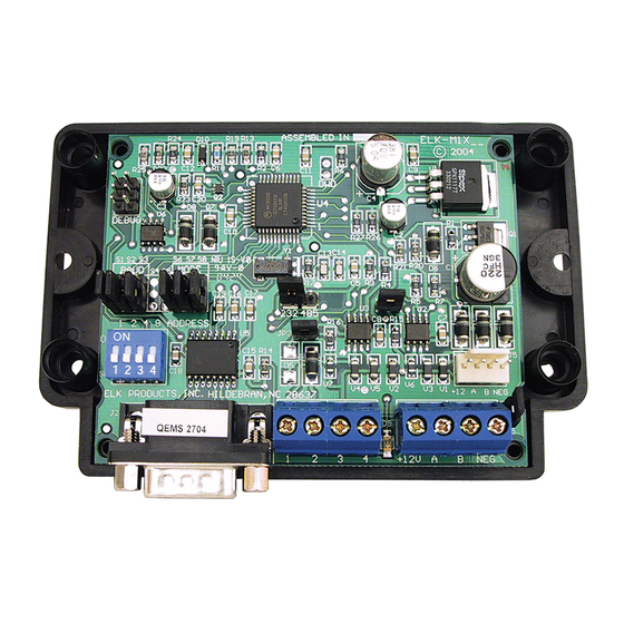
ELK-M1XSP
Lighting Interface, Thermostat Interface,
and Serial Port Expander
INSTALLATION
MANUAL
IMPORTANT NOTICE: Every effort has been made to assure the accuracy of the information contained in this docu-
ment as of the date printed.
The extent of integration between Elk Products and other Partner Mfgs varies from product to product. Some integra-
tion is more powerful or feature rich than others. In some cases there are variables or limitations not within Elk's
control which may render certain desirable features unavailable or unusable. Certain Partner Mfgs products and/or
protocols, including Elk's may not contain the capabilities or data definitions to permit additional integration beyond
what is currently available. In addition, Partner Mfgs may, at their option, add, modify, or discontinued features or
support with little or no notification.
Drawings, illustrations, diagrams, part numbers, etc. contained and shown in this document are provided as refer-
ence only. All information is based on equipment available from or provided by the Partner Mfg. at the time the
information was created. A Partner Mfg may in fact offer similar or alternative equipment in their line that Elk has not
evaluated, and therefore Elk cannot guarantee operational compatibility.
For reasons stated herein, Elk Products makes no warranty that it will be able to integrate all available features or
operations, nor does it make any express or implied warranties of fitness for a particular purpose or of merchantability.
Refer to Elk's Limited Warranty.
Specifications are Subject to Change without notice.
PO Box 100
3266 US Hwy 70 West
Hildebran, NC 28637
828-397-4200 828-397-4415 Fax
M1XSP Rev. G 5/2/2011
Printed in USA
http://www.elkproducts.com
Advertisement
Table of Contents

Related Manuals for Elk Products ELK-M1XSP

Summary of Contents for Elk Products ELK-M1XSP
- Page 1 Elk cannot guarantee operational compatibility. For reasons stated herein, Elk Products makes no warranty that it will be able to integrate all available features or operations, nor does it make any express or implied warranties of fitness for a particular purpose or of merchantability.
-
Page 2: Table Of Contents
APPLICATION: The ELK-M1XSP is a "3 in 1" product. As a lighting interface, it adapts the M1 Control to many brands of Lighting control products which use “serial" communications. As a thermostat interface, it adapts the M1 Control to HVAC Serial Communicating Thermostats. -
Page 3: General Installation And Setup
General Installation and Setup INSTALL UNIT * SET ADDRESS AND OPTION JUMPERS * ACTIVATE M1 BUS ENROLLMENT PROCESS J1 -Factory JP3 - Jumper selects Use ONLY! between RS-232 or RS-485 Jumpers JP1 - Jumper selects S1,S2,S3 select termination of M1 BAUD rate RS-485 Data Bus JP2 - Jumper selects... -
Page 4: Updating/Replacing Firmware In The Elk-M1Xsp
60.x.x Field Installable Firmware: Advantage Air HVAC only. {Australia} (Downloadable from Elk M1 Website) 70.x.x Field Installable Firmware: HAI OmniStat and OmniStat 2 Thermostats (Downloadable from Elk M1 Website) Updating/Replacing Firmware in the ELK-M1XSP The M1XSP stores it’s operating firmware in “Flash” memory. This state-of-the-art memory allows electronic field updates and eliminates the old fashion method of changing IC chips or shipping boards back to the factory. -
Page 5: Aprilaire 8870 Thermostat
JP3 to the "232" position. The BAUD jumpers S1,S2, & S3 do not matter as the Aprilaire baud rate is preset internally. Plug the Aprilaire supplied 6 ft RJ to DB9 Cable between the 8811 Protocol Adapter and the ELK-M1XSP. DO NOT USE THE ELK-WO37A CABLE. -
Page 6: Rcs Tr16 (Rs-232 Format) Thermostat
Install, and wire the RCS Control Unit and Wall Display Unit to the HVAC system per the RCS instructions. Install the ELK-M1XSP per the instructions on page 3. Be sure to enroll the device into the M1. Set the MODE jumpers S5=1, S6=0, S7=0, & S8=1 for RCS mode. If the M1XSP has jumper S4, set it to =1. Set Jumper JP3 to the "232"... -
Page 7: Rcs Tr16/Tr40 (Rs-485 Format) Thermostats
Install, and wire the RCS Control Unit and Wall Display Unit to the HVAC system per the RCS instructions. Install the ELK-M1XSP per the instructions on page 3. Be sure to enroll the device into the M1. Set the MODE jumpers S5=1, S6=0, S7=0, & S8=1 for RCS mode. If the M1XSP has jumper S4, set it to =1. Set Jumper JP3 to the "485"... -
Page 8: Hai Omnistat 1 (Rc) & Omnistat 2 Series (Rs-232) Themostats
Install the ELK-M1XSP and set its data bus address from 1 to 4 using the 4-position dip switch. IMPORTANT: The data bus address MUST be coordinated with the OmniStat address as follows: The M1XSP data bus address MUST be 1 when connected to OmniStats addressed as 1, 2, 3, or 4. - Page 9 Wiring Diagram for OmniStat 1 Series ** Older M1XSP units won't have the S5 and/or S4 Jumpers MODE HAI = 1010 ** Jumper JP3 S5 S6 S7 S8 ELK-M1XSP must be in 232 Interface position. Shorting plug on S1 S2 S3...
-
Page 10: Carrier Infinity Hvac System 'Themostat
Automation Connection (RS-232) Port on the Infinity System Access Module "SAM" model # SYSTXCCSAM01. The SAM supports two (2) Carrier Infinity HVAC systems. Each system can support eight (8) zones. The ELK-M1XSP can communicate with up to 16 Thermostats. Refer to LIMITATIONS AND NOTES BELOW. The firmware in the M1XSP MUST be manually updated to version 40.0.6 or greater. -
Page 11: Lighting Controllers With Rs-232 "Serial" Interfaces
Install Lighting Controller using the instructions provided by the manufacturer. If the Lighting Controller's interface has an address setting then set it to address 1. Most controllers do not require an address setting. Install the ELK-M1XSP per the instructions on page 3. Set Jumper JP3 to the "232" position. -
Page 12: Onq-Alc - (Individual Lighting Switches)
RS-485 proprietary network. An OnQ ALC Serial interface is required for interfacing the Master Controller Interface with the ELK-M1XSP, and then into the M1 line of controls. The M1XSP supports 31 ALC modules (dimmers, switches on each of 4 branches for a total of 124 individually addressable ALC devices. The M1XSP also supports ALC 4 button scene switches, provided they are wired and connected on ALC branch 1. - Page 13 OnQ-ALC - (continued) M1 Lighting Devices Mapped to OnQ ALC The PLC column is for reference only. OnQ-ALC OnQ-ALC Light (X-10) (X-10) Branch/Node/SS OnQ-ALC Light (X-10) OnQ-ALC Light (X-10) Light Branch/Node/SS Device # Ref. Branch / Switch Ref. Branch / Switch Device # Ref.
-
Page 14: Upb - (Individual Lighting Loads And Links)
UPB is a PLC or Powerline Communications lighting technology. There are 2 methods for interfacing UPB to M1. First is an ELK-M1XSP connected to a UPB PIM 'S" (RS232 Serial Program Interface Module). Second is a new product called the ELKM1PCSPIM (or PCSPIM 'E'). - Page 15 UPB - (continued) M1 Lighting Devices Mapped to UPB The PLC column is for reference only. Light (X-10) (X-10) (X-10) Light Light (X-10) Light Device # Ref. Ref. Ref. Device # Ref. Device # Device # Switch 65 Switch 129 Link (Scene) 01 Switch 1 Switch 2...
-
Page 16: Centralite (Individual Lighting Loads And Scenes)
An ELK-M1 or ELK-M1EZ8 Controller. One (1) ELK-M1XSP Serial Port Expander. NOTE: Firmware updates may be downloaded from the ELK M1 Dealer Web site. Centralite LiteJet or Elegance with MCP processor board, JetStream with RS232 Bridge, or Starlite with MCP base unit. - Page 17 Centralite - (continued) M1 Lighting Devices Mapped to Centralite The PLC column is for reference only. Light (X-10) Centralite Centralite Light (X-10) Centralite Light (X-10) Centralite Light (X-10) Device # Ref. Ref. Ref. Device # Device # Ref. Device # Load 129 Scene 01 All On Load 1...
-
Page 18: Lutron Radiora - (Phantoms, Zones, Security Flash/Solid, Master Ctrl Buttons)
Serial Interface, Dimmers, Keypads, etc. Operation limited to Phantoms, Zones, Security Flash/Solid, & Master Ctrl Buttons. 1. Install the ELK-M1XSP per the instructions on page 3. Be sure to enroll the device into the M1. 2. The M1XSP jumper settings should be: JP3=232 position and JP5=ON, Mode Jumper S4=1 (not all boards have S4 jumper) S5=0, S6=1,S7=1, and S8=0. - Page 19 Lutron 1st Generation RA - (continued) M1 Light Devices 177 thru 248 correspond to Lutron RA buttons on Master Control units 1 thru 12. Unused (unassigned) buttons can be used, with restrictions, to initiate rule triggers in the M1. Buttons that are already assigned to activate or display phantoms or zones SHOULD NOT BE USED as rule triggers simply because the state of the button can be out-of- sync with the M1, preventing a transition change from occurring.
-
Page 20: Insteon - (Individual Lighting Loads And Scenes)
1) INSTEON Interface > Powerlinc Modem (PLM p/n 2412S) communicating to a ISY Controller produced by Universal Devices Inc. The ISY connects to the M1Control over a LAN network, utilizing Elk's M1XEP Ethernet Adapter. NO ELK-M1XSP is required if using an ISY Controller. This is perhaps the easiest and most powerful way to interface with INSTEON, as it offers Computer setup and management of the devices in a powerful and easy to use Graphical User environment 2) INSTEON Interface >... - Page 21 INSTEON - (continued) Set the M1XSP Jumper JP3="232". Using the ElkRP software, program the M1 or M1EZ8 attributes for Lighting devices 1 through 192 as follows: Format = Serial Expander, Type = Dimmer (Type may alternately be On/Off Switch if device does not support dimming). These first 192 M1/EZ8 lighting devices may now be "linked"...
- Page 22 To erase all the linked devices from memory in the ELK-M1XSP: 1. Power down the M1XSP and move the S1 jumper to the 0 position.
- Page 23 INSTEON - (continued) M1 Lighting Devices Mapped to INSTEON The PLC column is for reference only. Light (X-10) (X-10) INSTEON INSTEON (X-10) INSTEON INSTEON Light Light (X-10) Light Device # Ref. Ref. Device # Ref. Device # Device # Ref. Device 65 Device 129 Group 01...
-
Page 24: Leviton Viziarf (Zwave) Lighting
LEVITON ViziaRf (ZWave) Lighting Interfacing to the Leviton ViziaRf Lighting can be accomplished using the ELK-M1XSP connected to the Leviton VRCOP RS232 Serial Interface. This permits functional support for ZWave 2-Way Lighting and a few specific ZWave Thermo- stats. The firmware in the M1XSP MUST be manually updated to version 20.0.x or greater. Firmware updates may be obtained from the Elk website. -
Page 25: Uplink 2500 And Anynet Cellular Radios
ELK-M1G/M1EZ8 must be version 4.3.8 or greater and ElkRP Remote Program Software must be version 1.6.2 or higher. Install the ELK-M1XSP per the instructions on page 3. Set MODE Jumpers on the M1XSP to 1 0000: S4* ="1" (UP), S5="0" (DN), S6="0" (DN), S7="0" (DN), & S8="0" (DN). -
Page 26: W800Rf32 X-10 Rf Receiver
*Some boards MAY NOT have the S4 jumper. The position of BAUD jumpers S1,S2,S3 does not matter. IMPORTANT NOTE: Software and firmware revisions required are: ELK-M1XSP at version 1.0.14 or greater. The following X-10 Radio Transmitters have been tested with the W800RF32 into an M1XSP: Model HR12A, Home Automation Remote Control. -
Page 27: Aes Intellinet Radio Subscriber Unit
AES Intellinet Radio Subscriber Unit This document describes how to interface an AES Intellinet Radio Subscriber unit to an ELK-M1 or EZ8 Control using an M1XSP Serial Port Expander containing a dedicated firmware version. Reporting includes Contact ID formatted data of all events and conditions to the Central Station IMPORTANT: For AES compatibility the M1XSP must be flashed with "dedicated"... - Page 28 D. Program the reporting format as "7-Serial Expander". E. Program the Dial Attempts to a value of at least 1. F. Choose the desired conditions to be reported by clicking on the selection blocks at the bottom. G. Program the Account Number to be reported for each active Area (Partition). From the Communicator Reporting Code menus (folders), program the following: H.
-
Page 29: Data Bus E.o.l. Termination - Very Important
Data Bus E.O.L. Termination - VERY IMPORTANT! The control uses a RS-485 “differential” data bus operating at 38,400 bits per second. This is relatively high speed by industry standards and ensures fast, accurate communications. EOL data bus terminating resistors are strongly suggested to eliminate the possibility of reflection errors due to varying cable lengths. - Page 30 The ELK-M1DBHR † "Active" Data Bus Hub Retrofit splits the Controls' main RS-485 Data Bus into 4 managed RS-485 branches. Each branch can have 2 parallel home run cables for a total of 8 home runs. The last (end of line) device on each home run should be jumper terminated to insure proper operation and supervision.
- Page 31 [THIS PAGE INTENTIONALLY LEFT BLANK] M1XSP Installation Manual Page 31...
-
Page 32: M1Xsp Compatibility, Jumper Settings And Misc. Information
M1XSP Compatibility, Jumper Settings and Misc. Information M1XSP options are set by the placement of black shorting plugs on gold plated jumper pins . Some have 3 pins with a selection of "0" or "1". Some have only 2 pins with a selection of Off or On. Options vary by manufacturer. Refer to detailed installation and hookup diagrams. Partner Interface Settings for Jumpers Special setup, notes, and comments...
Need help?
Do you have a question about the ELK-M1XSP and is the answer not in the manual?
Questions and answers