
Related Manuals for Solinst 464 Mk3


Summary of Contents for Solinst 464 Mk3
- Page 1 Model 464 Mk3 Electronic Pump Control Unit User Guide September 24, 2019 #109652 Rev. C...
-
Page 3: Table Of Contents
Model 464 Electronic Control Unit User Guide - Contents 1.0 Introduction 1.1 Operating Principles 1.2 Model 464 Electronic Control Unit Specifications 1.3 Control Panel 1.4 LCD Display 2.0 Control Unit Operation 2.1 Start Up 2.1.1 Main Menu 2.2 LCD Contrast 2.3 About 2.4 Preset Flow Rates 2.5 User Flow Rates... -
Page 5: Introduction
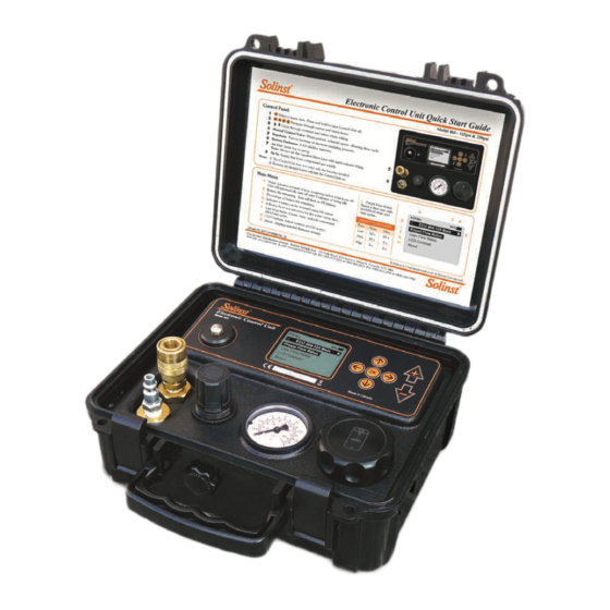
Model 464 Electronic Pump Control Unit User Guide 1.0 Introduction 1.1 Operating Principles The Model 464 Electronic Control Unit controls the supply of compressed gas Pneumatic Pump to pneumatic pumps. Drive (pressure) and vent periods are cycled to provide Operating Principles: water flow. -
Page 6: Control Panel
Model 464 Electronic Pump Control Unit User Guide 1.3 Control Panel NOTE Pressing any key will turn the OK button: selects a highlighted menu item (also toggles between lower Control Unit on (except Manual and uppercase letters and pressure units). Press and hold for at least 3 seconds Control button). -
Page 7: Control Unit Operation
User Flow Rates: allows you to create user-defined flow rates, save flow rates, select and edit saved flow rates. LCD Contrast: enables you to adjust the brightness of the display. About: will display information about the Control Unit, including firmware version and Solinst contact information. 4:59 Min NOTE ECU 464-125 Main... -
Page 8: Lcd Contrast
Model 464 Electronic Pump Control Unit User Guide 2.2 LCD Contrast To adjust the contrast of the LCD display, use the keys. 4:59 Min LCD Contrast Set: Figure 2-3 LCD Contrast 2.3 About Selecting this menu item will display information about the Model 464 Control Unit, including the installed firmware version. -
Page 9: User Flow Rates
Model 464 Electronic Pump Control Unit User Guide When “Start” is highlighted, pressing OK will start the pumping cycle. When the Control Unit is running the LCD will display the progress of the vent and drive periods. Pressing the OK button when in running mode will stop the cycle. 4:59 Min Low Flow Preset Drive: 17 of 50s... -
Page 10: Edit Settings
Model 464 Electronic Pump Control Unit User Guide Delete Settings To delete the setting, use the left arrow key to highlight the delete icon press OK. After pressing OK, a prompt will be displayed to confirm the deletion. 4:59 Min Saved Settings Delete site W13 Landfill 34... -
Page 11: Create Setting
Model 464 Electronic Pump Control Unit User Guide 2.5.2 Create Setting NOTE To create a new setting, select “Create Setting” from the User Flow Rates See Section 3.3 for help calculating menu. Enter the new site name, drive/vent times, and pressure setting using drive and vent times. -
Page 12: Manual Drive/Vent Cycles
Model 464 Electronic Pump Control Unit User Guide 2.7 Manual Drive/Vent Cycles NOTE The 464 Electronic Control Unit can also be operated manually if preferred. It The maximum output pressure of provides an alternative if the battery power runs out. the Electronic Control Unit is 125 psi or 250 psi, depending on the Unit. -
Page 13: Pumping Instructions
Bottle operation. Quick Drive Exhaust Line NOTE When using a Solinst 12 Volt Compressor, or any other air compressor, it is recommended Supply to use the 464 External Filter. See Line Section 4 for more details. 12 Volt... -
Page 14: Calculating Drive And Vent Times
Model 464 Electronic Pump Control Unit User Guide 3.3 Calculating Drive and Vent Times NOTE No bubbles usually indicates Bladder Pumps – Drive Time insufficient pressure. • Submerge the sample line in a beaker/container of water • Push the Manual Control Button on the Electronic Control Unit •... -
Page 15: Double Valve Pumps - Drive Time
Model 464 Electronic Pump Control Unit User Guide Double Valve Pumps – Drive Time NOTE • Place the sample line into an empty collection container You can start with the sample line submerged. A steady stream of bubbles and then water discharge indicates sufficient pressure is being used. -
Page 16: Pump Optimization
Model 464 Electronic Pump Control Unit User Guide 3.4 Pump Optimization Bladder Pumps • Select and start your desired flow rate from the User Flow Rates menu. • If higher flow rate is required, stop the drive/vent cycle to allow editing of the set up. -
Page 17: Accessories
Model 464 Electronic Pump Control Unit User Guide 4.0 Accessories NOTE The 12 Volt Compressor connects to the Model 464 Electronic Pump Control When using a compressor, the drain at the base of the tank should be Unit using the 464 Supply Line. It is ideal for low flow applications of less than opened on a daily basis to prevent 100 ft (30 m) depths. -
Page 18: Maintenance
Model 464 Electronic Pump Control Unit User Guide 5.0 Maintenance Moisture in the Model 464 Electronic Pump Control Unit can shorten the lifetime of some of its components. After each sampling session, compressed air or nitrogen should be sent through the Pump Control Unit to ensure that any build-up of moisture is purged and pushed out of the Pump Control Unit, as well as through the Supply and Drive Lines. -
Page 19: Storage
Model 464 Electronic Pump Control Unit User Guide 6.0 Storage The Pump Control Unit should be purged with compressed air after use, as described in Section 5.0, then stored in a dry condition. Ensure the 464 External Filter is dry before storage. If the Pump Control Unit is going to be stored for longer than a two month period, the four alkaline batteries should be removed to avoid any potential leakage. - Page 20 High Quality Groundwater and Surface Water Monitoring Instrumentation Solinst Canada Ltd., 35 Todd Road, Georgetown, ON L7G 4R8 Fax: +1 (905) 873-1992; (800) 516-9081 Tel: +1 (905) 873-2255; (800) 661-2023 instruments@solinst.com...
Need help?
Do you have a question about the 464 Mk3 and is the answer not in the manual?
Questions and answers