
Related Manuals for PVA Emergence PRO

Summary of Contents for PVA Emergence PRO
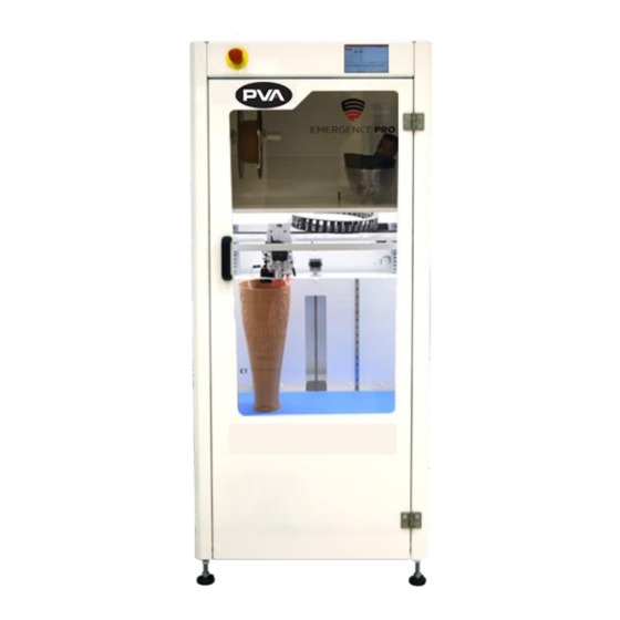
- Page 1 INNOVATION.PRECISION.EXCELLENCE. Emergence PRO™ 3D Printer Operation Manual Revision C...
- Page 2 Emergence PRO™ 3D Printer Manual This document is based on information available at the time of its publication. While efforts have been made to ensure the contents of this manual are accurate, the information contained herein does not purport to cover all specific details or variations in hardware, or to provide for every possible contingency in connection with installation, operation, or maintenance.
-
Page 3: Table Of Contents
Exhaust Flange Installation ..................12 Initial Setup ..........................13 Setting Up the Printer ....................13 Setting Up the Emergence PRO™ Wireless Connection.......... 15 Connect Web Interface to Existing Network ............. 17 M587 Command ......................18 Change Web Interface to Client Mode ............... 20 Emergence PRO™... - Page 4 Emergence PRO™ 3D Printer Manual G-code Files ........................47 Run Test Prints ....................... 48 Run G-Codes ........................48 Monitoring the Print Process....................49 First Layer ........................49 Next Layers ........................49 Opening the Door and Pausing the Print ..............49 Filament Break Detection System ................
- Page 5 Emergence PRO™ 3D Printer Manual Layer Shift ........................57 Clogged Nozzle ........................ 57 Materials Errors ....................... 57 APPENDIX A ..................... 58 Printing Terminology ......................58 APPENDIX B ..................... 59 Printer Dimensions and Parts ..................... 59 X-/Y-Assembly ........................60 Z Assembly ........................61 Print Head .........................
-
Page 6: Introduction
Before you operate this system, read the operation and setup manual. This will help you to become familiar with the product and ensure successful operation. If any questions or problems arise, contact PVA’s Technical Support department. PVA Contact Information Main Office... -
Page 7: Safety
Emergence PRO™ 3D Printer Manual Safety Certain warning symbols are affixed to the machine and correspond to notations in this manual. Before operating the system, identify these warning labels and read the notices described below. Not all labels may be used on any specific system. - Page 8 Emergence PRO™ 3D Printer Manual In situations where inattention could cause either personal injury or damage to equipment, a warning notice is used. Do not smoke near the machine. Always have a fire extinguisher available for emergency use. Before performing any repairs or maintenance to the system, turn off power and lock out the power disconnect switch.
-
Page 9: Best Practices
Emergence PRO™ 3D Printer Manual Best Practices • Do not wear loose clothes or jewelry when you operate the printer • Do not touch the print head while it is moving • Immediately engage the Emergency Stop button if personnel is in danger •... -
Page 10: Getting Started
Emergence PRO™ 3D Printer Manual Getting Started Unboxing 1. Remove the packaging straps from the shipping crate. 2. Open the shipping crate by first taking the lid off and then removing the sides. 3. Remove plastic wrapping around the metal ramp and any additional items that may be included. -
Page 11: Local Ventilation Disclaimer
Emergence PRO™ 3D Printer Manual 5. Secure the metal ramp to the wooden pallet on the side of the printer with lag screws from prior step. 6. Offload the 3D printer using the metal ramp with two people -- one person in front of the printer and one person in the back. -
Page 12: Exhaust Flange Installation
Emergence PRO™ 3D Printer Manual Exhaust Flange Installation If local ventilation is required, follow the steps below to install the exhaust flange. Remove cover from exhaust flange mount in the top rear corner of the machine. Figure 4: Remove Exhaust Flange Cover Locate the 4-inch exhaust flange provided with the machine. -
Page 13: Initial Setup
Emergence PRO™ 3D Printer Manual Initial Setup Setting Up the Printer 1. Remove additional packing material from the outside of the printer. 2. Remove the key tied to the handle on the front door. The key is for the back door. -
Page 14: Figure 9: Nozzle Brush Box
Emergence PRO™ 3D Printer Manual 5. Unbox the nozzle brush from the box that is shipped with the printer. Figure 9: Nozzle Brush Box 6. Install the nozzle brush in the hole on the front left of the print bed. -
Page 15: Setting Up The Emergence Pro™ Wireless Connection
Figure 11: Connect Power Cord Setting Up the Emergence PRO™ Wireless Connection The Emergence PRO™ has 2.4GHz wireless network connection capability that allows you to use the printer remotely with a computer. For the initial setup of the printer, you will need to use this feature. -
Page 16: Figure 13: Serial Number
Emergence PRO™ 3D Printer Manual Note: The serial number is listed on the label located in the upper right corner of the back panel of the printer. Figure 13: Serial Number 4. The password for the network is PVA12345. This should not be needed next time you connect. -
Page 17: Connect Web Interface To Existing Network
The process to do this will be specific to your network hardware and you may need consult the manufacturer. 2. Use the steps outlined in Section 2.3.2 to connect to the Emergence PRO’s WiFi network. 3. Once connected, access the Web Interface. -
Page 18: M587 Command
Emergence PRO™ 3D Printer Manual M587 Command The M587 command will be used to send your desired network information to the web interface’s G-code console. The M587 command must include three components. • S: Network SSID o Must be enclosed in quotation marks o Case-sensitive •... -
Page 19: Figure 16: Enter M587 Command
Emergence PRO™ 3D Printer Manual 1. In the Send G-code field, enter the full M587 command. 2. Click Send. Once received by the printer, if formatted correctly, you will see the M587 shown in green within the system messages. Figure 16: Enter M587 Command Additional Commands: •... -
Page 20: Change Web Interface To Client Mode
Emergence PRO™ 3D Printer Manual Change Web Interface to Client Mode Confirm Network Connectivity 1. Navigate to Macros to via web interface or printer’s HMI. 2. Select the Set Wi-Fi Client Mode macro. 3. The printer will temporarily switch to client mode and attempt to connect to the assigned network until there is a power cycle or emergency stop. -
Page 21: Figure 18: Edit Config.g File
Emergence PRO™ 3D Printer Manual 8. Navigate to the Network section. To select a network, a semicolon must be placed in front of the network and removed from the other networks. Figure 18: Edit Config.g File 9. Delete the semicolon (;) from M552 S1. -
Page 22: Figure 20: Reboot Confirmation
Figure 20: Reboot Confirmation 13. The web interface will confirm the file was successfully updated. Figure 21: File Updated 14. The control screen on the Emergence PRO will confirm that the machine is connected to the network. Figure 22: Network Connection Confirmation... -
Page 23: Figure 23: Control Screen Wifi Confirmation
The green popup will disappear after 10 seconds. Figure 23: Control Screen WiFi Confirmation Note: The Emergence PRO can also be powered down so the SD card storing the config.g file can be removed from the controller. Within the system file of the SD card is the Config.g file. -
Page 24: Emergence Pro™ Setup
Emergence PRO™ 3D Printer Manual Emergence PRO™ Setup Printer Tool Kit Before starting the setup process, locate the Tool Kit included with your printer. The following items are included and shown below. Figure 24: Printer Tool Kit 1. Roll of blue tape 8. -
Page 25: Check Levelness Of The Bed Relative To The Gantry
Emergence PRO™ 3D Printer Manual Check Levelness of the Bed Relative to the Gantry 1. Check the status on the Printer Control Screen in the upper right corner. It should say Idle (Figure 25). 2. If it reads Standby, undo the red Emergency Stop button located on the front upper left corner of the machine. -
Page 26: Figure 26: Leveling Values Displayed
Emergence PRO™ 3D Printer Manual Note: If connected to the web interface, the message can be found under the G-code Console. o The first value will be for the rear right leveling screw. This will typically be 0. o The second value will be the amount of adjustment required for the left leveling screw;... -
Page 27: Adjust Bed Level
Emergence PRO™ 3D Printer Manual Adjust Bed Level 1. If adjustments are needed, loosen the hex nut on the left and front right leveling screw on the bottom of the bed with a 7 mm wrench (Figure 28). The tools are included in the Printer Tool Kit. -
Page 28: Figure 29: Rotate Leveling Screw
Emergence PRO™ 3D Printer Manual 2. Adjust the leveling screws according to the values displayed (Figure 29). • 1.00 turn – equivalent to a full rotation of the screw. • 0.50 turn – equivalent to a half rotation of the screw. -
Page 29: Check Bed Levelness
Emergence PRO™ 3D Printer Manual 5. Once the three points of the bed level are within +/- 0.12 turn, lock the leveling screws in place. o To lock the leveling screws, hold the leveling screw in place with a 2mm hex key then tighten hex nut with 7mm wrench. -
Page 30: Figure 31: View Results Via Web Interface
Emergence PRO™ 3D Printer Manual 4. After the Check Bed macro is complete, view the results via web interface. 5. Click the dropdown arrow next to Auto Bed Compensation (Figure 31) and select Show Mesh Grid Heightmap. Figure 31: View Results via Web Interface 6. -
Page 31: Install And Gap Hot End
Emergence PRO™ 3D Printer Manual 6. Hover over a point or double click a probe point to view the resulting measured height and position (Figure 32). 7. The resulting four z-values should all be within +/-0.5 mm left to right and front to back. -
Page 32: Figure 34: Inserting Hot End
Emergence PRO™ 3D Printer Manual 4. Release the red hot end clamp handle on the hot end receiver block by pulling it forward (Figure 34). 5. Fully insert a Hot End into the hot end receiver block and clamp. The white cables should face the front and the blue cables should be accessible. - Page 33 Emergence PRO™ 3D Printer Manual 6. Fully insert the Filament Guide Tube into the hot end via the Filament Guide Tube Collet. Ensure the guide tube is fully inserted and bottomed out within the hot end. 7. Plug in the white Heater Cartridge Connector into the slot labeled C.
-
Page 34: Figure 35: Temperatures For Installing Hot End
Emergence PRO™ 3D Printer Manual 9. On Printer Control Screen, set the Active Bed Temperature to the appropriate print temperature for the filament you will use by selecting the Active Temp button. 10. Enter the desired temperature and press Set. -
Page 35: Figure 36: Set Active Temperatures
Emergence PRO™ 3D Printer Manual 15. Once the hot end and print bed are at temperature, home the printer by pressing Auto Homing Button (Figure 36). 16. On Printer Control Screen, select Move. In the Move Head screen and in Z-values, press -50 twice to move bed up about 100 mm. -
Page 36: Remove Hot End
Emergence PRO™ 3D Printer Manual Remove Hot End After the filament is removed, perform the steps below: 1. Remove the Filament Guide Tube. 2. Remove the white Heater Cartridge Connector in the slot labeled C. 3. Remove the blue Thermistor Connector in the slot labeled D. -
Page 37: Figure 38: Filament Load
Emergence PRO™ 3D Printer Manual Figure 38: Filament Load Figure 39: Shaft Collars Page 37 of 68 Revision C December 2020... -
Page 38: Figure 40: Extrusion
Emergence PRO™ 3D Printer Manual 7. Via the Extrusion button on the printer display, quickly extrude 200 mm to prime the hot end (Figure 40). • In the Extrusion Amount, press 100 twice. • In Speed, select 50. • Press Extrude. -
Page 39: Unload Filament
Emergence PRO™ 3D Printer Manual Unload Filament 1. On the Printer Control Screen, select Move and press 50 once in Z values to lower print bed 50 mm. 2. On Printer Control Screen, set the Active Hot End Temperature to the appropriate print temperature for material. -
Page 40: Figure 42: Test Print Files
Emergence PRO™ 3D Printer Manual 2. Select Test Prints (Figure 42). Figure 42: Test Print Files 3. The test prints loaded onto Card 0, which is part of the Printer Control Screen, will be listed. Select a test print for the filament loaded and hot end installed. Select Print. -
Page 41: Print
Emergence PRO™ 3D Printer Manual Print Printer Control Screen The printer control screen is a touch screen controller consisting of four screens: Control, Print, Console, and Setup. See Figure 12 on next page. Stop Button Stops and reboots printer. Bed Button Sets bed to active state or standby. -
Page 42: Figure 43: Printer Control Screen
Emergence PRO™ 3D Printer Manual 14 Control Screen Main menu for the control screen. 15 Print Screen Similar to the control screen and only used when printing. Allows for pause, resume, and cancel commands. 16 Console Screen Displays codes and commands recently entered in the printer. -
Page 43: Starting The Print
Emergence PRO™ 3D Printer Manual Starting the Print The Emergence PRO™ allows for a G-code to be loaded through a MicroSD card or through a network upload. Once you have acquired your G-code, you can use either option. MicroSD 1. Copy the G-code file from your PC to a MicroSD card. -
Page 44: Figure 46: Microsd Button
Emergence PRO™ 3D Printer Manual 3. Press the MicroSD card button on the Printer Control Screen. Figure 46: MicroSD Button 4. On the MicroSD screen, press the MicroSD card icon to switch between the onboard SD card (Card 0) and the secondary SD card on the top of the machine (Card 1). -
Page 45: Figure 48: Select G-Code
Emergence PRO™ 3D Printer Manual 5. Select a desired G-code to run. Figure 48: Select G-code 6. Select Print. Figure 49: Print Page 45 of 68 Revision C December 2020... -
Page 46: Internet Upload
2. To upload a new file from the Web Interface, click Upload & Start in the upper right- hand corner of the Web Interface Home Screen. Figure 50: Emergence PRO™ Web Interface Home Screen 3. When prompted, select the desired G-code to print. -
Page 47: G-Code Files
Emergence PRO™ 3D Printer Manual 5. Once Open is selected, the file will be uploaded to the printer and the print will begin. This file will be saved on Card 0, which is inserted into the printer controller. Figure 52: Upload Complete A status bar will show the progress of the G-code file upload as it is being transmitted wirelessly to the printer. -
Page 48: Run Test Prints
Emergence PRO™ 3D Printer Manual Files can be uploaded by browsing for them or dropping them onto the Upload G Code Files(s) button. The file upload functionality cannot be used while the machine is running. Right-click on a G-code file to display a list of options. From here, you can run the dispense part (Print File), estimate the dispense path time (Simulate File), or download the G-code file (Download). -
Page 49: Monitoring The Print Process
2. To resume printing, select Print and then press Resume. The Emergence PRO™ also includes a door sensor that will pause an active print when opening the front door. This function acts as an added layer of protection for the printer and operators. -
Page 50: Helpful Recommendations
A relative humidity level of 10% is ideal for storing filament, however, anything under 30% is acceptable. Filament may also be left in the top of the Emergence PRO™ with the dehumidifier for a short period of time. Filament should be stored in the aforementioned container for long term storage. -
Page 51: Cleaning And Maintenance
Rail Maintenance The Emergence PRO™ uses linear guide rails for all axes. Maintaining these rails takes a small amount of synthetic lubricant applied once per month. In the printer kit is a small bottle of synthetic lubricant. To lubricate the rails: •... -
Page 52: Check For Quality
Emergence PRO™ 3D Printer Manual Check for Quality Many print quality issues associated with 3D printing are a result of incorrect slicer settings or variance in filament from manufacturer to manufacturer. However, if you continue to experience the same issues with different slicer settings, there may be a mechanical issue. - Page 53 Emergence PRO™ 3D Printer Manual Inconsistent texture: Inconsistent texture can be a sign of moist filament, under extrusion, and poor layer adhesion. If the filament finish is not as expected, moisture within the filament is likely the reason. Overheating: This can cause drooping, poor layer adhesion, and gaps in the print. To solve this, first check if the fans are on.
-
Page 54: Quick Tips
Emergence PRO™ 3D Printer Manual Quick Tips As you gain more experience, you will be able to judge how to best address issues with prints. To get you started, here are some tips. • Printing slower (5% to 10%) and colder (5° to 10°) will help with print quality. -
Page 55: Troubleshooting
Emergence PRO™ 3D Printer Manual Troubleshooting Probe Failed to Extend 1. Manually pull down the probe tip and ensure nothing is binding or damaged. 2. Wipe the probe shaft with isopropyl alcohol. 3. Run the Reset Probe macro option. 4. The probe will extend and retract then should be a solid red. -
Page 56: Over Extrusion
Emergence PRO™ 3D Printer Manual Over Extrusion If there is excess filament coming out of the hot end, follow the steps below. 1. Reduce the extrusion percentage on the Printer Control Screen or Web Interface. Note: Filament diameters can occasionally be over diameter. -
Page 57: Print Appears Cloudy
Emergence PRO™ 3D Printer Manual Print Appears Cloudy If the print appears cloudy, the filament is not dry. Consult the filament manufacturer for the appropriate drying procedure. Layer Shift If a print unexpectedly shifts in the middle of a print, follow the troubleshooting steps below. -
Page 58: Printing Terminology
Emergence PRO™ 3D Printer Manual APPENDIX A Printing Terminology 3D Model Any digital shape occupying three dimensions. Extruder Allows for filament to be extruded; includes the hot end. Feed Rate The speed at which the extruder moves filament. Flow Rate The volume of filament extruded per unit time. -
Page 59: Printer Dimensions And Parts
Emergence PRO™ 3D Printer Manual APPENDIX B Printer Dimensions and Parts Figure 55: Printer Dimensions Page 59 of 68 Revision C December 2020... -
Page 60: Y-Assembly
Emergence PRO™ 3D Printer Manual X-/Y-Assembly A breakdown of the X-/Y-assembly. Figure 56: X-/Y- Assembly Page 60 of 68 Revision C December 2020... -
Page 61: Z Assembly
Emergence PRO™ 3D Printer Manual Z Assembly Figure 57: Z Assembly Print Head Page 61 of 68 Revision C December 2020... -
Page 62: Figure 58: Print Head 1
Emergence PRO™ 3D Printer Manual Figure 58: Print Head 1 Page 62 of 68 Revision C December 2020... -
Page 63: Figure 59: Print Head 2
Emergence PRO™ 3D Printer Manual Figure 59: Print Head 2 Page 63 of 68 Revision C December 2020... -
Page 64: Technical Specifications And Warnings
Emergence PRO™ 3D Printer Manual Technical Specifications and Warnings Build Volume 480 mm X 330 mm X 635 mm (19 in x 13 in x 25 in) Volts: 120/220V (Refer to machine serial tag) Power Requirements Amps: 10A Frequency: 50/60Hz Hot End Temperature Limit Up to 285°C (518°F) -
Page 65: Recommended Maintenance Schedule
Emergence PRO™ 3D Printer Manual APPENDIX E Recommended Maintenance Schedule Task Frequency Date Last Performed Once per Recharge Dehumidifier Week Once per Check Belt Tension Month Every 5 Clean Hot End prints Once per Lubricate Rails Month Every 3 to 6... -
Page 66: Table Of Figures
Emergence PRO™ 3D Printer Manual Table of Figures Figure 1: Remove Plastic Wrapping ..................... 10 Figure 2: Remove Metal Plates ......................10 Figure 3: Secure Metal Ramp to Wooden Pallet and Move Printer ..........11 Figure 4: Remove Exhaust Flange Cover................... 12 Figure 5: Exhaust Flange ........................ - Page 67 Figure 47: MicroSD Screen ........................44 Figure 48: Select G-code ........................45 Figure 49: Print ............................45 Figure 50: Emergence PRO™ Web Interface Home Screen ............46 Figure 51: Select G-code and Open....................46 Figure 52: Upload Complete ........................ 47 Figure 53: G-code Files .........................
-
Page 68: Warranty
Unauthorized repair or modification of the enclosed product, and/or the use of spare parts not directly obtained from PVA (or from factory authorized dealers) will void all warranties.
Need help?
Do you have a question about the Emergence PRO and is the answer not in the manual?
Questions and answers