
Summary of Contents for TechnoKom TKLS
- Page 1 TKLS • USER MANUAL DOCUMENT VERSION 1.11 FUEL LEVEL SENSOR USER MANUAL TechnoKom © 2014...
-
Page 2: Table Of Contents
TKLS • USER MANUAL Table of content Software Copyright Notice ..........................Safe Operation and Installation ........................Introduction ................................Product Overview ..............................Technical Specification ............................Scope of Supply ..............................Components of Sensor ............................. Interface Connectors ............................Getting started ..............................Sensor Connection ............................ -
Page 3: Software Copyright Notice
TechnoKom or third parties. Laws of the Russian Federation and other countries secure certain exclusive rights of TechnoKom and third parties to the software, which is subjected to copyright, for example, exclusive rights for distribution or reproduction. -
Page 4: Introduction
To ensure the best performance of the TKLS, it should be installed and set up only by qualified specialists. The TKLS sensor can operate both as a part of a fuel monitoring system and as a part of a fleet management system. For proper operation of the TKLS sensor, the customer should be... -
Page 5: Product Overview
TKLS • USER MANUAL Product Overview The TKLS fuel level sensor is designed to measure fuel level in a vehicle fuel tank and transfer this information to external devices via one of the supported interfaces. The TKLS can be used as a replacement of the factory-fitted standard fuel level sensor or as an additional sensor for fuel level monitoring. -
Page 6: Technical Specification
TKLS • USER MANUAL Technical Specification Description Value RS-485 (TIA/EIA-485-A), Output Interface Frequency output Protocols for RS-485 AGHIP / LLS / ModBus Bluetooth (BLE) Built-in Accelerometer / Inclinometer Automatic calibration Self-diagnostic Error Report Remote Configuration via Bluetooth Remote Configuration via RS-485... - Page 7 In order to establish the communication between the AutoGRAPH controller and the TKLS sensor in AGHIP protocol, it is sufficient to enable the protocol in the controller as it is enabled in the TKLS by default and does not require any sensor re-configuration.
-
Page 8: Scope Of Supply
End cap (spare) – 1 pc. Fuse with holder – 1 pc. The figure given above shows just an example of the scope of supply which can differ from the real set delivered with the TKLS sensor. TechnoKom © 2014... -
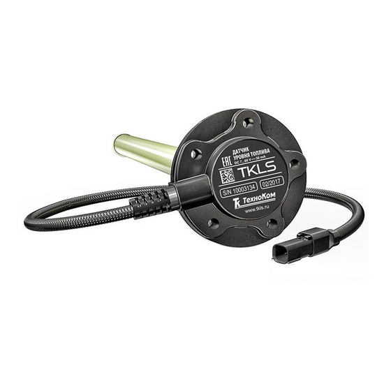
Page 9: Components Of Sensor
TKLS • USER MANUAL Components of Sensor Product identification Mounting hole (x5). Interface Connector 1 (male). FUEL LEVEL SENSOR 30 mA Sensor cover. Seal gasket. S/N 10003135 02/2015 Measuring probe. www .tkls.eu End cap Sealing hole (x4). 1 Device designation contains trademark and contact details of the manufacturer, device description, serial number and release date of the device. -
Page 10: Interface Connectors
TKLS • USER MANUAL Interface Connectors Interface Connector 1 (male) Connector 2 (female) View from side of pins View from side of sockets. This is the connector of the signal cable supplied with the sensor. № Wire Colour Assignment +Vin... -
Page 11: Getting Started
TKLS • USER MANUAL Getting started Before installation it is highly recommended to check the sensor for any mechanical damage. Select sensor installation area • The sensor location depends on the geometric form of the tank and should be chosen in such a way as to provide accurate readings regardless of fuel movement in the tank during vehicle motion. - Page 12 TKLS • USER MANUAL • Before drilling, ensure that there aren’t any baffle plates inside in the tank in the proposed sensor installation area within a radius of 20 mm. This can be checked by drilling a small hole (about 3 mm) in the installation area.
- Page 13 PC. To set an empty tank readings: • connect the TKLS sensor to the configuration tool following the instruction given in the help file for this software. The sensor readings of empty tank will be displayed on the Settings tab of the configuration tool;...
- Page 14 TKLS • USER MANUAL To set a full tank readings: • connect the TKLS sensor to the configuration tool following the instruction given in the help file for this application. • if the sensor is calibrated by inserting into a fuel storage, first turn the sensor upside down and pour about 10-20 ml of fuel into the measuring probes through the drain hole, e.g.
-
Page 15: Sensor Connection
If the wire is too short, it can be spliced with a wire of at least 0.5 mm2 cross section (20 AWG or thicker). The TKLS sensor can be connected to any external unit that supports ModBus or LLS protocols to transfer fuel level readings. -
Page 16: Power Supply Connection
• Connect the fuse supplied with the sensor to the “+Vin” line. The fuse should be placed as close as possible to the point where the TKLS is connected to vehicle power system. • Connect Connector 2 of the signal cable to the male Connector 1. -
Page 17: Rs-485 (Tia/Eia-485-A) Bus Connection
• any third-party device equipped with RS-485 bus and supporting LLS or Modbus protocol. When connecting TKLS-L to RS-485 bus of an external device, be careful not to cross the “A” and “B” wires, otherwise correct operation of the sensor is not guaranteed. Also ensure that TKLS-L sensor IMPORTANT and all external devices to be connected to the RS-485 bus are disconnected from the power supply. -
Page 18: Frequency Output Connection
TKLS sensor. When connection to the AutoGRAPH controller, the sensor must be connected to one of the active low digital inputs of the controller (inputs 1-4).Before connecting to the TKLS-L, the input of the AutoGRAPH must be switched to Frequency Mode. -
Page 19: Auto Calibration
The transferred fuel volume is measured by a flowmeter which output is connected to digital input of the TKLS sensor. At each calibration step, when the required fuel volume has been transferred in the tank, the sensor waits until the fuel fluctuations in the tanks stop and takes measurements with the specified timeout. - Page 20 TKLS • USER MANUAL • Then select Menu File – Settings... in the configuration tool; Fig.2. Calibration settings. • In the Settings menu (Fig.2), set up the flowmeter parameters – a number of pulses accounted for 1 litre of fuel. This characteristic is given in technical documentation on the flowmeter;...
- Page 21 • While calibration, calculated calibration points are added in the calibration table on the Auto calibration tab. Current readings of the TKLS sensor are displayed at the top of the table – current fuel level in liters, appropriate sensor readings in the form of ADC stages and frequency;...
-
Page 22: Error Codes
-125 frequency out of calibration range -124 built-in accelerometer fault Diagnostic operation can be performed using the “TKLS configuration tool”. If an error is occurred, this will be shown in the program window. Fig.5.Sensor diagnostics. TechnoKom © 2014... -
Page 23: Sensor Configuration
• connect the USB cable to the PC (fig.1, step 2); • connect free end of the adaptor (Molex connector) to TKLS sensor (fig.1, step 3); • if the sensor drivers have been installed previously, connected device will be automatically recognized by the system. -
Page 24: Driver Installation
AutoGRAPH fleet management device which the sensor is connected to. Also the sensor supports remote configuration via Bluetooth. NOTE For more information on the TKLS Configuration Tool see “TKLS Configuration Tool” help file. Driver Installation This section covers an installation procedure of the TKLS driver. For proper operation the AGUSB Driver must be installed before the sensor connection to a PC. -
Page 25: Modbus Register Mapping
TKLS • USER MANUAL Modbus Register Mapping The TKLS is capable of communication via the RS-485 serial bus in the Modbus/RTU protocol. The TKLS supports the Modbus function 03 – Read Holding Registers. Address (HEX) Description 0x00 TKLS address 0x01... -
Page 26: Appendix
TKLS • USER MANUAL Appendix APPENDIX 1: SAE-5 MOUNTING. APPENDIX 2: BUILD-IN ACCELEROMETER AXES ORIENTATION. TechnoKom © 2014... - Page 27 TKLS • USER MANUAL FUEL LEVEL SENSORS TechnoKom ltd. Copyright © Chelyabinsk, 2016 www.tk-nav.com All Rights Reserved. info@tk-nav.com TechnoKom © 2014...
Need help?
Do you have a question about the TKLS and is the answer not in the manual?
Questions and answers