Table of Contents
Advertisement
Quick Links
Installation and Instruction
A. Failure to read and follow all instruction carefully before installing or
operating this flow switch could cause personal injury and/or
property damage. Save these instructions for future use.
B. NOTE FOR SAFETY
Warning
Never remove the cover when power is applied. This can result in electric shock.
Connect wiring after turning off power. This can result in electric shock.
Do not sprinkle water over the microswitch. This can result in electric shock.
Do not connect a load exceeding the electric rating. This can result in bad contacts.
Do not turn screws other than the operating value setting screw.
Incorrect operations or water leakage can occur.
Install the switch so that the arrow indication and the fluid flow match.
The switch does not work if fluid flows in the opposite direction.
In addition, paddles can be damaged.
Use fluid that does not corrode the liquid contacting material. In addition, use
fluid in liquid form. Gas or liquid mixed with gas causes unstable operations.
Connect the switch to ground. Do not connect the grounding wire to a gas pipe,
water pipe, lightning rod or the grounding wire of a telephone line.
If the grounding is not appropriate, this can result in electric shock.
Use fluid with flow velocity of 2m/s or less. In addition, avoid strong pulsating
fluid and vibration. Paddle can be damaged.
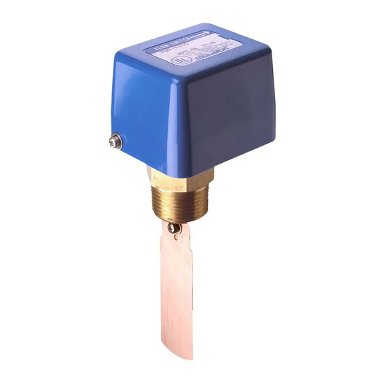
C. DESCRIPTION
Type FQS Flow Switch with SPDT micro switch detects the fluid flow in pipe line.
The electric contact block is completely sealed from the fluid in the pipe line by a bellows.
When a flow rate increases,the actuating plate⑦ will move while the resistant force ordering.
D. SPECIFICATIONS
・Structure
Open
・Liquid contacting material
Copper alloy
or stainless paddle(option)
・Maximum operating pressure
0.98 MPa
・Allowable fluid temperature
5 to 80 ℃
・Endurance operations
100,000 operations
・Mounting screw
R1(MPT) or NPT(option)
・Ambient temperature
-25 to +80 ℃
・Ambient humidity
80 %RH or less
(No freezing, no condensation)
・Contact structure
Single-pole double-throw
・Electrical ratings
Type name,
Resistive
Lamp
Voltage
symbol
load
load
125V AC
15
1.5
Standard
250V AC
15
1.25
(G)
30V DC
6
1.5
0.5
0.5
125V DC
DC high load type
125V DC
10
1.5
(D)
250V DC
3
1.5
PLRCA.PI.GK0.A1.02 / 520H3006
C
Flow rate increase
A: Normally open terminal
B: Normally closed terminal
A
B
C: Common terminal
Unit: A
Motor
Type name,
Minimum
Voltage
load
symbol
applicable load
5
Small load type
24V DC
0.01
3
(K)
100V AC
0.01
5
0.05
5
2
Approved by
drawn by
date
Name
1991
PADDLE TYPE FLOW SWITCH
APR.
4
5
6
7
8
FLOW
Maximum
current load
0.1
0.1
© Danfoss Saginomiya
Catalog Number
FQS
Terminal
3
2
1
MARK
Screwed in depth
Paddle 1
№
Parts Name
Paddle 2
1
Label
2
Insulated Plate
Paddle 3
3
Micro Switch
4
Adjusting Screw
Metal Fitting For
5
Flow Adjusting Screw
6
Flow Adjusting Screw
7
Actuating Plate
8
Adjusting Spring
Drawing Number
1/2
A-QS-90003-A
Q'ty.
1
1
1
1
1
1
1
1
Advertisement
Table of Contents

Related Manuals for Saginomiya FQS

Summary of Contents for Saginomiya FQS
- Page 1 Paddle can be damaged. MARK C. DESCRIPTION Type FQS Flow Switch with SPDT micro switch detects the fluid flow in pipe line. The electric contact block is completely sealed from the fluid in the pipe line by a bellows. Screwed in depth When a flow rate increases,the actuating plate⑦...
- Page 2 65A (2 / B) by a defect or failure of the Product. 1+2+3 (3B) 1+2+3 100A 100A (4B) (4B) 1044 1+2+3 125A (5B) 1265 1613 1266 1342 1+2+3 150A (6B) 1780 2268 1781 1890 FEB.12.2004 REVISION K.Suzuki PLRCA.PI.GK0.A1.02 / 520H3006 © Danfoss Saginomiya...
Need help?
Do you have a question about the FQS and is the answer not in the manual?
Questions and answers