
Summary of Contents for IRIS IRMA 6
- Page 1 Pos: 2 /IRMA-Sensoren_5._ Automatic Passenger Counting IRMA 6 Installation Manual IRMA6-SENSOR-HD-00-SWITCH-IO-00-(R) IRMA6-SENSOR-HD-00-SWITCH-00-(R) Rev. 1.4 12/2020...
- Page 2 These specifications do not claim to be error-free and will need to be updated or corrected. Such modifications may be made by iris-GmbH without notice. Characteristic or typical values given are based on our experience and are approximate values to be expected;...
-
Page 3: Table Of Contents
Table of content IRMA 6 overview ................................. 4 Mounting ..................................6 Mounting 2 sensors per door ..........................9 Connecting IRMA 6 (optionally with angled M12 connectors) ..............11 Ensuring power supply ............................14 Connector types ................................ 15 Configuring IRMA 6 ..............................16 IRMA 6 components .............................. -
Page 4: Irma 6 Overview
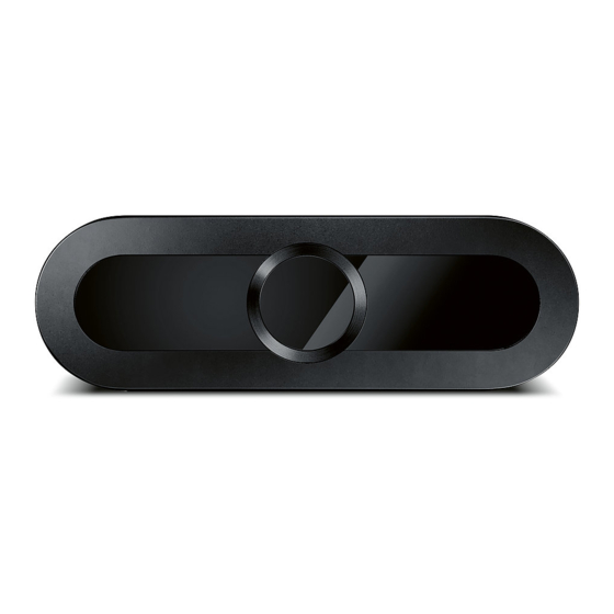
IRMA6-SENSOR-HD-00-SWITCH-(IO)-00-(R)(1) Installation Manual | Released IRMA 6 overview Fig. 1: IRMA 6 in vehicles – placement above doors, cross section in vehicle, door area in vehicle • The mounting height must not exceed 2.40 m (3 m in Table 1: Dimensions depending on door height preparation). - Page 5 10 M12 door contact connector (on demand) (f) 3 M12 Ethernet connector 7 Sensor unit 11 Interface unit 4 Leaf spring 8 Door panel IRMA 6 comes with normal M12 connectors or with angled M12 connectors to save space. Rev. 1.4 | 12/2020 5 / 27...
-
Page 6: Mounting
• Install IRMA 6 on a horizontal surface. The maximum permissible deviation from the ETH interface. horizontal plane is ±5°. 4. Perform a commissioning test on your pc or on-board computer. • IRMA 6 must be installed by staff that follows the pertinent regulations and the installation manual. Mounting Rev. 1.4 | 12/2020... - Page 7 Fit sensor unit into interface unit Inside Outside Put the IRMA 6 sensor unit via the mounting hook into the drilled hole Fit in in the internal connector and the attaching form of the senor unit in the door panel.
- Page 8 Connect IRMA 6 Angled M12 connectors, slewable (180°), optionally available. Connect IRMA 6 via (angled) M12 connectors to the Ethernet network, to voltage supply and optionally to the door contacts. Rev. 1.4 | 12/2020...
-
Page 9: Mounting 2 Sensors Per Door
IRMA6-SENSOR-HD-00-SWITCH-(IO)-00-(R)(1) Installation Manual | Released Mounting 2 sensors per door If a door is observed by 2 sensors, iris recommends the following installation parameters: Figure 1: Installation of 2 sensors per door Mounting height Sensor distance 2060 mm 780 mm Rev. - Page 10 IRMA6-SENSOR-HD-00-SWITCH-(IO)-00-(R)(1) Installation Manual | Released In a 2-doors scenario, the door contact signal is connected only to the master sensor. The master sensor is identified in the following way: Standing inside the vehicle, view from inside to the outside – the left sensor is the master sensor, the right sensor is the slave sensor. Rev.
-
Page 11: Connecting Irma 6 (Optionally With Angled M12 Connectors)
IRMA6-SENSOR-HD-00-SWITCH-(IO)-00-(R)(1) Installation Manual | Released Connecting IRMA 6 (optionally with angled M12 connectors) Connect IRMA 6 to power supply Connect IRMA 6 from component to the on-board power supply via the wire strands of the power supply cable K-M12POW-B-oE-04-2m. Mind the correct connection points (+, - and shield) in the connection block of the vehicle and See section "Ensuring... - Page 12 (external power supply from vehicle required). M12 door contact Variant 2 connector (f) See cabling diagram for wiring overview of IRMA 6 in the vehicle, see Fig. 3, p. 13. Rev. 1.4 | 12/2020 12 / 27...
- Page 13 IRMA6-SENSOR-HD-00-SWITCH-(IO)-00-(R)(1) Installation Manual | Released Fig. 3: Installation of IRMA 6 (Ethernet version) as door contact variant 1 IRMA 6 SWITCH variant (rear view on interface unit) 7 Adapter cable for PC connection for service Doors with 1 IRMA 6...
-
Page 14: Ensuring Power Supply
30 min minimum 3 Power cable for IRMA 6 K-M12POW- B-oE-04- 2m 4 IRMA 6 Fig. 4: Power supply of the IRMA 6 sensor with fuse and time relay for 30 min overrun power Rev. 1.4 | 12/2020 14 / 27... -
Page 15: Connector Types
IRMA6-SENSOR-HD-00-SWITCH-(IO)-00-(R)(1) Installation Manual | Released Connector types • Ethernet interface • Voltage supply connector • D-coded (f) • A-coded (m) • 5 poles • 5 poles • Ethernet interface • Optional GPIO • D-coded (f) connector for door contact • 5 poles •... -
Page 16: Configuring Irma 6
IRMA6-SENSOR-HD-00-SWITCH-(IO)-00-(R)(1) Installation Manual | Released Configuring IRMA 6 Provide a DHCP server in the LAN. Open DNS. Connect IRMA 6 via the RJ45 On the left side you find the navigation: service cable with your pc. Enter the device number in the browser bar. - Page 17 In the section “Installation Parameter” you set the parameters for the placement of IRMA 6 according to the measures in the vehicle. Measure the values for each installation parameter in the vehicle and enter them. (See graphics below for each installation parameter in vehicle).
- Page 18 If the installation distance exceeds 20 cm, absolutely contact iris-GmbH.Measure the distance and enter the value measured. Rev. 1.4 | 12/2020 18 / 27...
- Page 19 IRMA6-SENSOR-HD-00-SWITCH-(IO)-00-(R)(1) Installation Manual | Released Vehicle edge offset Rotation angle X positive value negative value positive angle negative angle Adhesive marker Side view Vehicle edge offset is the difference in level between the adhesive marker Rotation angle X is the inclination angle of the sensors visual axis (=x axis) and the vehicle edge with the door open.
- Page 20 IRMA6-SENSOR-HD-00-SWITCH-(IO)-00-(R)(1) Installation Manual | Released Left / right wall distance Left / right door clearance Left door Right door Right wall Left wall clearance clearance distance distance Top view Top view Left/right wall distance is the left-hand/right-hand sensor monitoring Left/right door clearance (passage width) is the horizontal distance area up to the left/right lateral boundary in the vehicle interior.
- Page 21 IRMA6-SENSOR-HD-00-SWITCH-(IO)-00-(R)(1) Installation Manual | Released Left / right door opening angle Top view Left / right door opening angle is the maximum door opening angle with In the section “Sabotage Detection” you check the field “Enable Sabotage the door opened, between the vehicle edge and the left / right door “Detection”...
- Page 22 Click APPLY to the set the data from all sections of CONFIGURATION. Wait until the green bar confirms that the configuration is applied. Click on ETHERNET to get to the IP configuration of IRMA 6. In the section “IP Configuration” you can, if needed, set: •...
- Page 23 IRMA6-SENSOR-HD-00-SWITCH-(IO)-00-(R)(1) Installation Manual | Released Click on LOG to see recorded error states. See the field “Log Level”, “Support Level” and “Number of Log Entries” for logged error messages. Click on VISUALISATION to visualize counting data. Rev. 1.4 | 12/2020 23 / 27...
- Page 24 See boarding and alighting persons in real-time. Via “Image Type” you can switch … “Intensity” error messages. viewing type between “Depth” and Click OK, if IRMA 6 needs to be restarted because of error messages recorded in the log. Rev. 1.4 | 12/2020 24 / 27...
-
Page 25: Irma 6 Components
IRMA6-SENSOR-HD-00-SWITCH-(IO)-00-(R)(1) Installation Manual | Released IRMA 6 components Table 2: Overview of IRMA 6 components - interface and sensor unit with cables Description Explanation Sketch / item description IRMA 6 sensor unit Connection possible with: interface unit of IRMA 6... -
Page 26: Check Of The Installation
Check of the installation 1. Have all IRMA 6 been installed and are they properly attached? 7. Do the infrared LEDs of IRMA 6 light up when the door is open? Please check 2. Is their mounting position correct? separately for each door! 3. -
Page 27: Drilling Templates
IRMA6-SENSOR-HD-00-SWITCH-(IO)-00-(R)(1) Installation Manual | Released Drilling templates There are 2 kinds of templates in (mm): • for retrofitting with hand tools • for original equipment manufacturers (CNC machining) Rev. 1.4 | 12/2020 27 / 27...
Need help?
Do you have a question about the IRMA 6 and is the answer not in the manual?
Questions and answers
Enter the device number in the browser bar,And how can i find the product of device number
To find the IRIS IRMA 6 product using the device number in the browser bar, follow these steps:
1. Ensure a DHCP server is available in the LAN.
2. Connect the IRMA 6 sensor to your PC using an RJ45 service cable.
3. Open a web browser on your PC.
4. Enter the device number in the browser's address bar.
5. This will allow access to the device for configuration, error checking, updates, and data visualization.
This process enables interaction with the IRMA 6 sensor for setup and monitoring.
This answer is automatically generated