Table of Contents
Advertisement
Quick Links
Advertisement
Table of Contents

Summary of Contents for Leader Scan
- Page 2 UWB device to search for buried victims by detecting movement Japanese patent: 10-54795 PCT (international patent): PCT/RU2005/000483 Product number LEADER Scan – English version D11.07.023 LEADER Scan – Chinese version D11.07.024...
-
Page 4: Table Of Contents
INTRODUCTION ........................6 Presentation of LEADER Scan .................... 6 Composition of LEADER Scan .................... 6 Detailed technical features ....................7 DESCRIPTION OF LEADER Scan .................... 8 Control box .......................... 8 2.1.1 Description of control box ..................... 8 2.1.2 Control box connectors ....................9 2.1.3... - Page 5 4.11 Record function ......................... 35 4.12 Right/Left hand function ....................36 Use in the field ........................37 Physical positioning of UWB sensor .................. 37 Detection through materials ....................39 Recommendations ......................40 Usage advice ........................40 Interpreting the signal on the oscillogram ................41 Automatic and Real Time modes ..................
-
Page 6: Introduction
1 INTRODUCTION 1.1 Presentation of LEADER Scan LEADER Scan uses UWB (Ultra Wide Band) technology to survey debris. It can be used to detect and locate victims buried under rubble after landslides, avalanches, collapses, explosions, etc. The victims are located using movement detection. This movement can be as small as the thoracic movements caused by breathing. -
Page 7: Detailed Technical Features
• Do not try to repair this product or replace parts (unless the manual gives you specific instructions on how to do this). Any maintenance or repairs should be carried out by your local dealer or the LEADER maintenance department. Watertight and... -
Page 8: Description Of Leader Scan
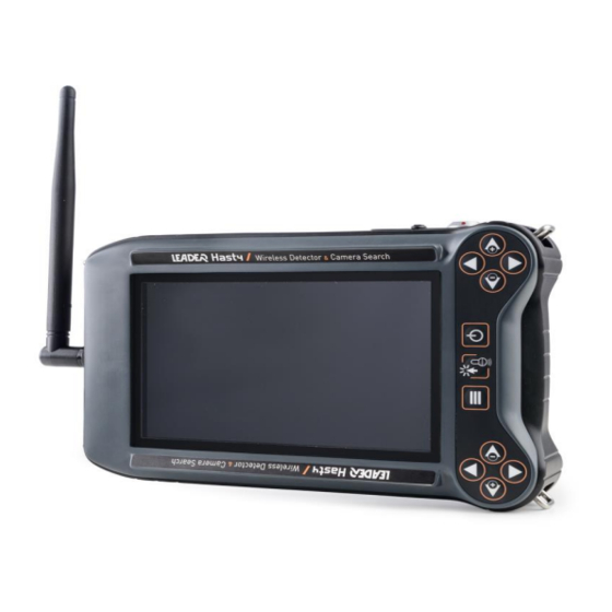
2 DESCRIPTION OF LEADER Scan 2.1 Control box 2.1.1 Description of control box ➢ The polypropylene control box is made up of: • 1 x 7in TFT 16/9 bright colour screen. • 1 keyboard to adjust settings and browse through different menus. -
Page 9: Control Box Connectors
2.1.2 Control box connectors To make it easier to connect accessories, each female connector for the control box is marked with a colour code and symbol. The antenna connector is The USB connector is marked with the USB symbol marked with the icon and a and a red colour code to connect to the male connector with the USB cable’s red sleeve. -
Page 10: Control Keyboard
2.1.3 Control keyboard The keyboard has photoluminescent buttons to make them easier to see in the dark. The keyboard is reversible so it can be used by a right or left-handed operator. To move from one to the other, the corresponding function must be selected. View in “Right hand use mode”: Up + / Down - buttons: - Navigate up/down the menu. -
Page 11: Powering The Control Box
2.1.4 Powering the control box The LEADER Scan control box is delivered with a polymer lithium battery pack with a 5 hour battery life which is inserted into the back of the control box. The battery can be charged whilst in the box, but the box cannot be used Charging can take place between 0°C min and 45°C max using the supplied charger. -
Page 12: External Sd Card For Recording
2.1.5 External SD card for recording A Class 10 micro SD card is inserted into the reader of every delivered control box. The number of recordings depends on their duration. However as an indication, taking the example of an average recording of 500KB, the SD card can hold up to 8000 recordings. The micro SD card reader is located under a panel on the back of the box. -
Page 13: Installation Of The Sun Shade
2.1.6 Installation of the sun shade If there is bright sunlight, the sun shade makes the screen darker to make it easier to read. To affix the sun shade on the control box, it must be positioned correctly on the front as indicated. The red lines indicate the correct position. -
Page 14: Uwb Sensor
2.2 UWB sensor 2.2.1 UWB sensor connectors 1/ USB connector to connect the UWB sensor in wired mode to the control box. 2/ Watertight cap for USB connector to protect it when not in use. 3/ ON/OFF button to switch on the UWB sensor. -
Page 15: Description Of The Uwb Sensor
2.2.2 Description of the UWB sensor The sensor detects movement in a cone area in a vertical position. The dimensions of the cone can vary depending on the nature of the debris. Material Pelicase ABS type case Technology UWB (Ultra-Wide Band) Search distance Up to 30m (90ft) in an unobstructed space for wide movements Variable depending on type of terrain: approximately 1050m3... -
Page 16: Uwb Sensor Power
2.2.3 UWB sensor power The LEADER Scan sensor power is 9 to 16 V. This is not dangerous for the operator but, in order to avoid any risk with the batteries, battery chargers, etc. Respect the security guidelines set out in the instruction manuals for these accessories. -
Page 17: Sensor Battery Charging
2.2.5 Sensor battery charging 1. Connect the CA plug of the VL-VPC1 IDX charger to the 100-240V socket. 2. Place the ENDURA CUE D75 battery in the charger. Battery charged The red LED turns red. The charging starts automatically if the battery is not fully charged. - Page 18 • Checking remaining battery life: To check the remaining battery life, press the side button. If the 3 LEDs switch on, this means that the battery is fully charged. • Battery storage (control box and sensor): If the batteries are not used for over 3 months, they must be stored at a temperature of 0 to 40°C and a charge level of 50 to 70%.
-
Page 19: Use
3 USE 3.1 Switching the control box on and off ➢ Place a charged battery in the box. Start: Press the On/Off button • A welcome screen appears whilst the software starts up. • When the device has started, this start screen appears if the sensor is not connected (WiFi or USB): The icon indicates that there is no SD card inserted, it can appear briefly during start-up even if an SD card is inserted whilst it is detecting it. -
Page 20: Connecting Sensor To Box
From the start screen you can: Read the files on the SD card by pressing on Menu, only available if the recording files are stored on the SD card. Connect the sensor to the box. Switch off the box. To switch off the control box, press and hold the ON/OFF button for 2 seconds. -
Page 21: Languages And Measurement Units
3.3 Languages and measurement units ➢ Languages: The LEADER Scan graphic interface was designed to be as intuitive as possible and easy to use (shortcuts, easy menu sequences and functions...) in the field. The icons are subtitled in English and Chinese depending on the chosen device reference. -
Page 22: Control Screen
3.4 Control screen ➢ Once the sensor is connected to the control box, the following screen appears: 1. Level of WiFi signal (sensor connection). If the sensor is connected with the USB cable, the corresponding icon appears. 2. Sensor battery level. 3. -
Page 23: Menu: Description Of Functions
4 Menu: Description of functions Each functionality is controlled from the control keyboard, either with the up + /down - arrowsor the right/left arrows (see chapter 2.1.3) Sensitivity: Adjustment of the UWB sensor’s sensitivity (5 sensitivity levels). Pointer: Allows positioning of the pointer on the side of the cone to adjust the distance and view the signal of this depth in the oscillogram. - Page 24 ➢ When the device starts, the menu appears as follows: There are two different menus, you can move from one to the other by pressing the menu button Or by using the up and down arrows. Without menu...
-
Page 25: Xpert Mode Function
4.1 Xpert mode function To move into Expert mode, press on outside the menu, the same to leave expert mode. The icon on the bottom of the screen moves to ON and now displays the distance at which the pointer is located as well as detection surface and detection volume. Detection surface area Detection volume It is possible to keep this expert mode to use the menu functions and adjust Mini, Maxi and Pointer... -
Page 26: Adjustment Of Search Parameters
4.2 Adjustment of search parameters For the Sensitivity, Pointer, Mini, Maxi and Brightness functions, adjustment is as follows: Scroll through the menu until you highlight the desired function. Once the function is highlighted. Use the arrows to directly adjust the chosen function. Press on a bar graph appears: modify the settings using the arrows. -
Page 27: Sensitivity Function
4.3 Sensitivity function This function helps adjust the sensitivity of the UWB sensor to be more or less sensitive. Sensitivity can be adjusted from 0 to 4. 0 = Reduced sensitivity to help ignore major surrounding movements which are too clear. However the device will be less successful in detecting weak movements. -
Page 28: Minimum Distance Function
4.5 Minimum distance function Selects minimum search depth located at the start of the detection cone. Minimum search depth (Mini) By default the Mini is set to 0m (0ft). When adjusting the minimum distance, the difference between the minimum and maximum does not change, the maximum distance is therefore modified at the same time as the minimum depth. -
Page 29: Screen Brightness Function
Adjust the “Mini” and “Maxi” depths to define the search zone. Go to the menu and select. Launch the “Real time” mode by pressing An orange triangle starts to flash at the top of the screen. The device takes 15 to 20 seconds to start before starting the scan. -
Page 30: Automatic Mode Function
To stop the search, select the “Real time” icon again and press The flashing orange triangle disappears. During a search in “Real time” mode, if several people/movements are found in the previously determined detection zone (cone), only the largest person/movement will be used and displayed. - Page 31 => Total displayed in the cone: 3 victims/movements: After analysing each section, the pointer (1) is positioned on the maxi of the section. 2 - Pointer Once the full scan is complete, the pointer is distance positioned at the level of the closest detected 3 - Oscillogram movement to the sensor, indicating this depth (2).
-
Page 32: Source Function
For a 0-30m search, LEADER Scan can detect up to 10 people: 1 per section (0-4, 4-8, 8-12, 9-12, 12-16, 16-20, 20-24 and 24-26m). The scan can last up to 10 minutes in this case (less if the victims are detected before 1 minute in some sections) For a 0-10m search, the device will divide the cone into 0-4, 4-8 and 8-10m. - Page 33 (If sensor in “Automatic” or “Real time” mode, Data capturing = On) -Mode: Recording in “Real time search” mode or “Automatic search” mode -Record format version 9: Software information (for use by LEADER technician) Use the arrows to navigate in the list and delete the desired file.
- Page 34 Whilst reading a recording, the sensor battery icon disappears. The file recorded on the SD card can only be accessed if the sensor is connected. When the box is switched on and the sensor switched off, if there are recordings on the SD card, the following screen appears: SD card inserted and file present To access the recordings list, click on “select”...
-
Page 35: Record Function
The recordings can only be read on the control box. To avoid any handling mistakes, the recorded files cannot be deleted from the LEADER Scan box. To delete the files or clear the SD card, you must use a computer. -
Page 36: Right/Left Hand Function
4.12 Right/Left hand function Allows the control box to be used by a left handed or right handed person. Go to the menu and select. Click on. The device moves to left handed mode, highlighting the “Left hand” icon. Once selected, the function inverts the image, as well as the functionality displays (menu and sub-menus) and the keyboard use. -
Page 37: Use In The Field
The LEADER Scan sensor can detect movement in a cone area in a vertical position. The rubble density extends the detection angle, as the debris acts like a lens for the UWB antenna. The UWB sensor search angle is 90°... - Page 38 From the determined grid pattern, the operator could move the pointer to a specific path as shown in the images above by applying the overlap described in the next paragraph: To have the clearest possible image of the situation, the operator must move around the controlled space as much as possible by positioning the sensor vertically and also, if the conditions allow, horizontally from other locations.
-
Page 39: Detection Through Materials
The compact size of the UWB sensor allows it to be inserted into cavities and gain several centimetres to increase the percentage success of detecting a victim. 5.2 Detection through materials ➢ The UWB sensor cannot detect through: - Metal plates. - Water, puddles and saltwater. -
Page 40: Recommendations
LEADER Scan cannot detect a victim who is behind or under a solid metal screen or water. The device cannot detect through damp conducting bodies, like wet clay. Damp soil is not ideal for UWB scanning as water acts as a shield against waves. -
Page 41: Interpreting The Signal On The Oscillogram
5.5 Interpreting the signal on the oscillogram The LEADER Scan combines a detection zone (cone) and an oscillogram (graph) of detected movements on the screen. Movements are interpreted on the curve. (Number of movements and intensities of these movements). If the curve is sine curve, the user is in the presence of repeated movement (breathing, victim tapping regularly...). - Page 42 The scale of the Y axis adapts to the signal intensity to balance the heights of the curve on the screen and therefore the movements detected in the field. The LEADER Scan remains one of several tools used when searching for buried victims. The emergency worker must understand that they must rely on other search equipment or...
-
Page 43: Automatic And Real Time Modes
3 search sub-zones (0-3m (0-9ft), 3-6m (9-18ft), 6-9m (18-27ft)), it takes up to 3 minutes to complete the search (1 minute to scan each 3m section). The automatic mode search time is longer but has the advantage of being easier (the user sees the search result on the screen). -
Page 44: Define The Search Distances
5.7 Define the search distances Modify the search distances based on the debris composition in the field and depending on the depth to be analysed. Real time search mode: A closer search zone (Mini-Maxi) helps provide higher sensitivity in the selected zone and less “noise” from the outside. If the user selects 2-5m (6-15ft), the noise at a distance under 2m (6ft) and a distance over 5m will be lower. -
Page 45: Storage
5.9 Storage Case A Pelicase type high visibility orange case allows you to store the entire system. (Control box + UWB sensor + accessories + backpack). Weight of case alone: 12kg Dimensions: 670 x 510 x 372 mm Weight of entire unit: 25 kg Case Sensor... -
Page 46: Appendix
6 APPENDIX “Detection cone” measurements (radiation pattern) depending on the depth (distance) determined with the “Mini” and "Maxi” functions:... -
Page 47: Options
- Additional battery charger for the UWB sensor (Ref. D11.07.016). - Additional battery for the control box (Ref. D11.04.341). 8 MAINTENANCE LEADER Scan and its accessories do not require maintenance, just some basic precautions: - Disconnect the batteries before long-term storage. - Recharge the batteries every 3 months. - Page 48 If the wireless connection is interrupted, one of the screens below with the icon “No wireless sensor” shows the reconnection time. If this occurs during an “Automatic” or “Real time” search, the search restarts automatically. It is relaunched and restarts. When connected with USB, the device displays this icon in the top left.
- Page 49 NOTES:...
-
Page 51: Warranty
LEADER's obligation under this warranty is specifically limited to replacement or repair of the device (or its parts), and only after LEADER has inspected the device and deems it to be defective due to the fault of LEADER. To qualify for this limited warranty, the purchaser must return the equipment to LEADER SAS in a timely manner after discovering said defect. - Page 52 Manual code : SCAN.00.ZN8.12.EN.1...
Need help?
Do you have a question about the Scan and is the answer not in the manual?
Questions and answers