Table of Contents
Advertisement
Advertisement
Table of Contents

Subscribe to Our Youtube Channel
Summary of Contents for Fermvision FVQ-6030APP
- Page 1 2 WIRE SYSTEM FVQ‐6030APP KIT & FVQ‐6030 KIT VIDEO DOOR PHONE SYSTEM INSTALLER MANUAL FVQ‐6016KP‐F FVQ‐6013/9013WIFI Please read the manual carefully before using the product. Please note that images and sketches in this manual may be different from the actual products 1 ...
-
Page 2: Table Of Contents
Contents Monitor Description .............................. 3 Door Station Description ............................... 4 Addressing the monitors (When using more than one monitor): ................ 5 Impedance Switch ................................. 5 Viewing Multiple Door Stations On The Monitor ...................... 6 Wiring Diagrams ................................ 7 Lock Wiring .................................. 16 Summary Keypad door station codes ......................... 23 Detailed Keypad Codes ............................... 24 Wi‐Fi Configuration .............................. 27 Dimensions Front Plate: 219.5 x 120mm (H x W) Backing Box: 203.5 x 104 x 46mm (H x W X D) Make sure the recess box is completely sealed to prevent water penetration 2 ... -
Page 3: Monitor Description
Monitor Description NO Name Description 1 Micro SD Socket for Micro SD 2 Power Indicator White LED when power on 3 Do Not Disturb Purple LED when function is enabled 4 Message Indicator Green LED when you have missed calls 5 Microphone 6 Screen 7 Inch Digital TFT LCD 7 Switch Bit 1‐ Bit 5 – Home address Bit 6 – Bit 7 – Master and slave selection 8 Connection Point BUS1&BUS2 – System connection bus 24V & GND – External Power supply (Not needed) COM & NO – Connector for external speaker SW+ & SW‐ : Connector for external door bell 9 Speaker ... -
Page 4: Door Station Description
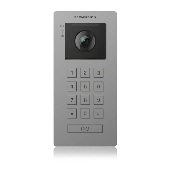
Door Station Description NO Name 1 Status Indicator 2 Camera 3 Speaker 4 Keypad 5 LED’s (Sensor located in middle) 6 Microphone 7 Fixing screw 8 Connection Port 4 ... -
Page 5: Addressing The Monitors (When Using More Than One Monitor)
Addressing the monitors (When using more than one monitor): This is controlled by dip switch 6 & 7 on the back of the monitor Type Dip Switch Setting Master Monitor Slave Monitor 1 Slave Monitor 2 Slave Monitor 3 Impedance Switch Only turn to the on position when the monitor is the end of line. This is controlled by dip switch 8 on the back of the monitor. Type Dip Switch Setting Impedance Off Impedance On 5 ... -
Page 6: Viewing Multiple Door Stations On The Monitor
Viewing Multiple Door Stations On The Monitor When using multiple door station you need to activate the door station to view on the monitors. Using the settings menu on each individual monitor type in the following code depending how many door station you have. (Default 4 Door Stations) Door Station Code (On) Code (Off) DS 1 0111 0110 DS 2 0131 0130 DS 3 0151 0150 DS 4 0171 0170 6 ... -
Page 7: Wiring Diagrams
Wiring Diagrams Notes: When using more than 1 door station you require a 4 branch Door station module FVQ‐6012D When using more than 1 monitor in star configuration you require a 4 branch monitor module FVQ‐6011M Door Station is addressed as number 1 by default 7 ... - Page 8 1 Door Station to 4 Monitors (Star Configuration) FRONT DOOR STATION # 1 Keypad Code 1234 #, 11#, 1#, *. 10A GP0 6011M BUS(IM) BUS(DS) 8 ...
- Page 9 MONITOR #1 MONITOR #2 MONITOR #3 MONITOR #4 BU S 1 B U S 2 BU S 1 BU S 2 BU S 1 B U S 2 BU S 1 B U S 2 6 5 4 3 2 1 6 5 4 3 2 1 6 5 4 3 2 1 6 5 4 3 2 1 Master...
- Page 10 1 Door Station to 3 Monitors (Series) FRONT DOOR STATION # 1 Keypad Code 1234#, 11#, 1#, *. 10A GP0 BUS(IM) BUS(DS) 10 ...
- Page 11 MONITOR #1 MONITOR #2 MONITOR #3 BU S 1 B US 2 BU S 1 BU S 2 BUS 1 BU S 2 6 5 4 3 2 1 6 5 4 3 2 1 6 5 4 3 2 1 Master Slave 1 Slave 2 11 ...
- Page 12 4 Door Station to 4 Monitors (Star Configuration) FRONT DOOR STATION #1 FRONT DOOR STATION #2 FRONT DOOR STATION #3 FRONT DOOR STATION #4 Keypad Code Keypad Code Keypad Code Keypad Code 1234 #, 11#, 1#, *. 1234#, 11#, 2#, *. 1234 #, 11#, 3 #, *. 1234#, 11#, 4#, *. 10A GP 0 A B C D DBC-4S...
- Page 13 MONITOR #1 MONITOR #2 MONITOR #3 MONITOR #4 B US 1 B US 2 B US 1 B US 2 B US 1 B US 2 B US 1 B US 2 6 5 4 3 2 1 6 5 4 3 2 1 6 5 4 3 2 1...
- Page 14 4 Door Station to 3 Monitors (Series) FRONT DOOR STATION #1 FRONT DOOR STATION #2 FRONT DOOR STATION #3 FRONT DOOR STATION #4 Keypad Code Keypad Code Keypad Code Keypad Code 1234#, 11#, 1#, *. 1234#, 11#, 2#, *. 1234#, 11#, 3#, *. 1234#, 11#, 4#, *. 10A GP 0 A B C D DBC-4S 6012 D BUS(I M) BUS(DS) ...
- Page 15 MONITOR # 1 MONITOR # 2 MONITOR # 3 B US 1 B US 2 B US 1 B US 2 B US 1 B US 2 6 5 4 3 2 1 6 5 4 3 2 1 6 5 4 3 2 1 Master...
-
Page 16: Lock Wiring
Lock Wiring The system has 2 Locks Lock 1 – 12 VDC (250mA) Output on exit or door release o Lock 1 is only power to unlock Lock 2 – Dry Collector that can be toggled between Normally Open or Normally Closed The Exit button can be configured in 3 Modes (Default is Lock 1 & Lock 2) Only Lock 1 Only Lock 2 Lock 1 and Lock 2 (DEFAULT MODE) 16 ... - Page 17 Power to Unlock Power to Lock Lock 1 N/A Lock 2 Exit Button To Open Lock 1 Lock 2 17 ...
- Page 18 Power to Unlock Power to Lock Lock 1 N/A Lock 2 Exit Button To Open Lock 1 Lock 2 10A GP0 88406 ‐ ‐ 12VDC EGRESS BUTTON EXIT BUTTON LOCK 2 1234#, 05#, 1#, *. 18 ...
- Page 19 Power to Unlock Power to Lock Lock 1 N/A Lock 2 Exit Button To Open Lock 1 Lock 2 Normally Closed 10A GP0 88406 ‐ ‐ 12VDC EGRESS BUTTON EXIT BUTTON LOCK 2 1234#, 05#, 1#, *. 19 ...
- Page 20 Power to Unlock Power to Lock Lock 1 N/A Lock 2 Exit Button To Open Lock 1 Lock 2 20 ...
- Page 21 Power to Unlock Power to Lock Lock 1 N/A Lock 2 Exit Button To Open Lock 1 Lock 2 Independent Exit button 21 ...
- Page 22 Power to Unlock Power to Lock Lock 1 N/A Lock 2 Exit Button To Open Lock 1 Lock 2 Independent Exit button 22 ...
-
Page 23: Summary Keypad Door Station Codes
Summary Keypad door station codes Description CODE Example (1234 is the Master Code) Adding a User Lock 1 (16‐25) Lock 1 – 1111 ‐ 1234#16#1111#* Lock 2 (36‐55) Lock 2 – 2222 ‐ 1234#36#2222#* Lock 1 lock time 04 5 Seconds – 1234#04#10#* Lock 2 lock time 03 5 Seconds – 1234#03#10#* Exit Button unlock type 05 Lock 1 Only – 1234#05#0#* Lock 2 Only – 1234#05#1#* Lock 1&2 Only – 1234#05#2#* Exit Button Delay to Activate 14 5 Seconds – 1234#14#10#* Door Station Address 11 Door Station 1 – 1234#11#1#* Door Station 2 – 1234#11#2#* Door Station 3 – 1234#11#3#* Door Station 4 – 1234#11#4#* Delete All Users 00 1234#00#* Change Master Code 01 Change code to 9876 – 1234#01#9876#* ... -
Page 24: Detailed Keypad Codes
Detailed Keypad Codes Adding a code: Input master code (1234 by default) and press #, then choose the lock group Lock 1 (starts from 16 up to 25 ) Lock 2 (starts from 36 up to 55 ) Press #, then input an access code ( from 4 up to 12 digits) and press #, Finally press * to exit. You can overwrite codes to modify or change codes. It is recommended to keep a list of users/address for future reference, No duplications allowed with any other codes. E.G: Input code 5029 into location 16: 1234#, 16#, 5029#, * Input code 2458 into location 36: 1234#, 36#, 2458#, * Lock 1 lock time: (Default 7 seconds) Input master code (1234 by default) and press #, 04#, input XX# (where XX goes from 1=0.5s, 2=1s...20=10 seconds) – XX is divided by 2 for seconds E.G: For an Lock 1 opening time of 7 seconds: press 1234#, 04#, 14#, *. Lock 2 lock time: (Default 7 seconds) Input master code (1234 by default) and press #, 03#, input XX# (where XX goes from 1=0.5s, 2=1s...20=10 seconds) ‐ XX is divided by 2 for seconds E.G: For an Lock 2 opening time of 7 seconds: press 1234#, 03#, 14#, *. ... - Page 25 Door Station address setting: Input master code (1234 by default) and press #, 11#, type X#(where X goes from 1 to 4) Default is 1 E.G: For Keypad door station 1: 1234#, 11#, 1#, *. For Keypad door station 2: 1234#, 11#, 2#, *. For Keypad door station 3: 1234#, 11#, 3#, *. For Keypad door station 4: 1234#, 11#, 4#, *. Delete All Users: Input master code (1234 by default) and press #, 00#, again input master code (1234 by default) and press #. E.G: 1234#, 00# * Changing Master code: Input previous master code (1234 by default) and press #, 01#, input new master code and press #. E.G: Changing master code to 3461: 1234#, 01#, 3461#. Temporary user code: Input master code (1234 by default) and press #, then choose the lock group Lock 1 (starts from 56 up to 59 ) Lock 2 (starts from 60 up to 63 ) Press #, then input an access code ( from 4 up to 12 digits) and press #, Finally press * to exit. It is recommended to keep a list of users/address for future reference, No duplications allowed with any other codes. After successfully unlocking the door the code will delete after 60 seconds. Within those 60 seconds you will be able to still use the code. ...
- Page 26 Ring Volume: Input master code (1234 by default) and press #, 15#, type X(where X is: 0 = Door station ringtone ON; 1 = Door station ringtone OFF) Default mode is On E.G: On: 1234#, 15#, 0#, * Off: 1234#, 15#, 1#, * Keypad Lights: Input master code (1234 by default) and press #, 02#, type X(where X is: 0 = Keypad lights on; 1 = Keypad lights Off) Default mode is On. If setting is on they will still only turn on during night time. E.G: On: 1234#, 2#, 0#, * Off: 1234#, 1#, 1#, * 26 ...
-
Page 27: Wi-Fi Configuration
Wi‐Fi Configuration Download the Smart phone application to configure WiFi Settings. Search for Fermvision WiFi For latest up to date instructions please visit https://shop.fermaxaus.com.au/support‐videos/ 27 ... - Page 28 Notes Slots or openings in the back of the monitor are provided for ventilation and to ensure reliable operation of the video monitor or equipment and to protect it from overheating. These openings must not be blocked or covered. All parts should be protected from violence vibration. Impact protection and not to be dropped or knocked. To clean the LCD screen, using hands or a wet cloth is forbidden To clean the equipment use a soft cotton cloth. No organic or chemical detergent. Image distortion may occur if the video door phone is mounted too close to magnetic fileds, e.g. microwaves, TV, fridges. Please keep away the monitor from wet, high temperature, dust, and caustic and oxidation gas in order to avoid any unpredictable damage. If devices are installed too close together noise interference can occur Do not open the device if you are unsure of causing damage. 28 ...
Need help?
Do you have a question about the FVQ-6030APP and is the answer not in the manual?
Questions and answers