Advertisement
Table of Contents
Lock-N-Load
ASSEMBLY & PREPARATION
Before using your new swage tool,
disassemble and carefully clean the dies,
removing the rust preventative. DO NOT
disassemble the swage punch assembly
(1) as it comes pre-set from the factory.
Any commercial solvent or cleaner, like
Hornady ONE SHOT
Gun Cleaner and
®
Dry Lube, will suffice. Reassemble the
swage die after cleaning.
Cartridge cases should be de-primed and
inspected. Discard those with cracks,
splits, or other visible defects. Make sure
case necks are round. You may need
to run an expander through them or full
length size the cases before swaging.
Primer pockets should be clean.
IMPORTANT: Sort cases by manufacturer
and lot number, if possible. Different
brands have varying web thicknesses,
which can cause swage variation.
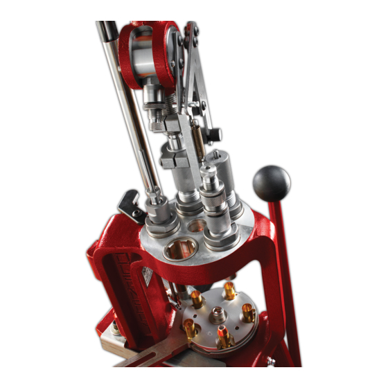
INSTRUCTIONS
Install swage plate assembly (5) onto
your Lock-N-Load
AP™. You will not
®
need a case retainer spring.
Raise the press ram to the top of its
stroke and thread the swage die (7) into
station 1 (Fig. A) until it makes contact
with the swage plate assembly. Back the
swage die off a half turn and tighten the
Sure-Loc
lock ring (3).
™
Thread the swage stripper die (2) into
station 3 (Fig. A) until it makes contact
with the swage plate. Tighten the
Sure-Loc
lock ring.
™
Thread the swage alignment die (6) into
station 4 (Fig. A) until it makes contact
with the swage plate. Tighten the
Sure-Loc
lock ring.
™
NOTE: The swage stripper die and
swage alignment die must be in contact
with the swage plate assembly while
the press ram is at the top of the stroke
to assure proper function of the swage
die without damaging the press.
AP
Primer Pocket Swage Tool
®
™
PARTS
1. SWAGE
PUNCH
ASSEMBLY
2. SWAGE
STRIPPER
DIE
3. SURE-LOC
LOCK RING
SWAGE DIE
ASSEMBLY
SWAGE
ALIGNMENT
DIE
Figure A
™
5. SWAGE
ASSEMBLY
SWAGE
STRIPPER
DIE
10. SWAGE
ADJUST
SCREW
9. LOCK RING
8. O-RING
7. SWAGE DIE
6. SWAGE
ALIGNMENT
DIE
PLATE
Insert a sorted case into the swage
alignment die mouth first. Lower the
press ram. The case will feed onto the
swage plate support stem.
With the swage adjust screw (10)
backed out of the swage die, cycle the
press until the inserted case enters the
swage die.
Thread the swage adjust screw down
until you feel resistance. Lower the
press ram about 1-inch and thread the
swage adjust screw down half a turn.
Raise the press ram. You should start
to feel the resistance when raising
the press ram. At this point, the primer
pocket crimp is starting to be swaged.
Adjustment for the proper amount
of swage is done by trial and error.
(OVER)
Advertisement
Table of Contents

Related Manuals for Hornady Lock-N-Load AP

Summary of Contents for Hornady Lock-N-Load AP
- Page 1 9. LOCK RING disassemble the swage punch assembly ASSEMBLY (1) as it comes pre-set from the factory. Any commercial solvent or cleaner, like 8. O-RING Hornady ONE SHOT Gun Cleaner and ® 2. SWAGE Dry Lube, will suffice. Reassemble the STRIPPER swage die after cleaning.
- Page 2 A properly swaged primer pocket. die allowing removal (Fig. B). Hornady Manufacturing Co. • P.O. Box 1848, Grand Island, Nebraska 68802-1848 308-382-1390 • 800-338-3220 • Fax: 308-382-5761 • Hornady.com/contact 15HMC0066 | 05/2015...
Need help?
Do you have a question about the Lock-N-Load AP and is the answer not in the manual?
Questions and answers