Table of Contents
Advertisement
Quick Links
Advertisement
Table of Contents

Subscribe to Our Youtube Channel
Related Manuals for Nidec 4P10


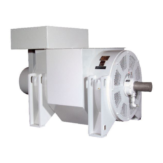
Summary of Contents for Nidec 4P10
- Page 1 Instruction Manual Installation Operation Maintenance AC Turbine Generator Publication 350-01016-00 En (October 2019) Kato Engineering, Inc. P.O. Box 8447 Mankato, MN USA 56002-8447 Tel: 507-625-4011 KatoEngineering@mail.nidec.com www.KatoEngineering.com Fax: 507-345-2798...
- Page 2 Please read this manual and all Publication Date Description included manuals in entirety before Revision unpacking, installing, and operating 350-01016-00 En October 2019 Updated document format. your generator. If your manual came 350-01016-00 Original document. on a CD, read all the files included on the CD.
-
Page 3: Table Of Contents
Contents Introduction Foreword Safety Instructions Ratings/Description Construction and Operating Principles Enclosures Stator Rotor Bearings Connection Boxes Excitation System PMG System Installation Receiving Inspection Unpacking and Moving Location Base Design Assemble to Prime Mover: Alignment Foot Deflection Doweling Electrical Connections Space Heaters Inspection Before Startup Storage of Kato Generators Remove generator from storage... - Page 4 Figures Previous Design - Opened Generator New Design - Opened Generator Previous Design - Totally Enclosed Generator New Design - Totally Enclosed Generator Generator Frame Generator Rotor Sleeve Bearing Typical Terminal Box Excitation System Excitation System Overview PMG System Rough Alignment Angular Alignment Parallel Alignment Field Flashing...
-
Page 5: Introduction
Introduction WARNING: Shock hazard—Do not Foreword service the generator or other electrical machinery without de-energizing and This manual contains instructions for installing, operating and tagging the circuits as out of service. maintaining Kato Engineering AC brushless revolving field generators. Dangerous voltages are present, which These generators are manufactured in many sizes and ratings and with could cause serious or fatal shock. -
Page 6: Previous Design - Opened Generator
OPENED MACHINES: 4P10, 4P10.5, 4P10.7, 4P11, 4P12, 4P63 BEARING LINER EXCITER SLEEVE/SHAFT EXCITER/PMG FRAME DIODE/RECTIFIER ACCESS COVER EXCITER/PMG FRAME END COVER PMG ROTOR PMG STATOR CORE & WINDING DIODE/RECTIFIER EXCITER ROTOR EXCITER STATOR CORE & WINDING OUTBOARD AIR SEAL OUTBOARD OIL SEAL... -
Page 7: Previous Design - Totally Enclosed Generator
TOTALLY ENCLOSED MACHINES: 4P10, 4P10.5, 4P10.7, 4P11, 4P12, 4P63 BEARING LINER EXCITER SLEEVE/SHAFT EXCITER/PMG FRAME DIODE/RECTIFIER ACCESS COVER EXCITER/PMG FRAME END COVER PMG ROTOR PMG STATOR CORE & WINDING DIODE/RECTIFIER EXCITER ROTOR EXCITER STATOR CORE & WINDING OUTBOARD AIR SEAL... - Page 8 Page 8...
-
Page 9: Construction And Operating Principles
Construction and Operating Principles Enclosures The standard design is open drip proof. The following options may apply to your generator: • Air filtered • Air-to-air heat exchanger cooled (TEAAC/CACA) • Air-to-water heat exchanger cooled (TEWAC/CACA) • Weather Protected II • IP 22, IP 23, IP 25, IP 44, IP54 •... -
Page 10: Rotor
Rotor The main rotor assembly is the revolving field. It consists of windings in a core, which is in turn mounted on a steel shaft. The exciter armature assembly and permanent magnet generator (PMG) rotor are also mounted on the shaft as are the fan(s) and other optional accessories. -
Page 11: Bearings
Bearings NOTE: If your generator has split roller bearings instead of sleeve bearings, The sleeve bearings may be self lubricated or force fed from a separate consult the bearing manual included in oil system. Temperature detectors monitor the operating conditions of the documentation package. -
Page 12: Excitation System
Excitation System The excitation system consists of the exciter stator assembly and the exciter armature assembly. See Figure 9. The exciter stator assembly consists of windings in a core. The core is made from steel laminations that are stacked and welded together. The main exciter stator coils are placed in slots in the core and form alternate north and south poles. -
Page 13: Pmg System
Excitation System Functional Overview Exciter field control is established by the strength of the exciter field current developed by the voltage regulator system. The DC voltage and current levels of the exciter field signal from the voltage regulator varies depending upon the generator output voltage and the loading of the output lines. -
Page 14: Pmg System
PMG System Functional Overview The PMG system functions as a pilot exciter, providing power to the automatic voltage regulator power supply. The PMG is an AC generator that uses permanent magnets in the rotor instead of electromagnets to provide the magnetic field. See Figure 11. Figure 11 PMG System Page 14... -
Page 15: Installation
Installation WARNING: Be alert at all Receiving Inspection times when installing, operating and maintaining the generator. Avoid contact Before accepting a shipment, examine the packaging for any sign of with the uninsulated metal parts of the damage that might have occurred during transit. Report any damage generator. -
Page 16: Assemble To Prime Mover: Alignment
Assemble to Prime Mover: Alignment NOTE: Mounting of the indicators must allow complete rotation of the prime Two-Bearing Alignment mover. Follow the tolerances specified by the coupling manufacturer when Use dial indicators that are rigid so indicator sag won’t be a factor. Using the they are less than described in this manual. -
Page 17: Angular Alignment
Figure 13 Angular Alignment Parallel Alignment: Fasten a dial indicator to one of the coupling halves, and scribe the position of the dial button on the top of the opposite coupling half as shown in Figure 14. Rotate both shafts simultaneously, keeping the finger or button on the indicator at the reference mark on the coupling hub. -
Page 18: Foot Deflection
Foot Deflection After alignment, check for foot deflection or “soft foot” condition on each shim location to eliminate distortion of the generator frame. Do this by loosing one mounting bolt at a time and checking deflection after tightening. Deflection at the shim location from shims under compression to a loosened condition must not exceed 0.003 inch. -
Page 19: Inspection Before Startup
Inspection Before Startup After electrical connections have been made, perform the following checks: • Check all the connections to the electrical diagrams provided. • Secure all covers and guards. • Turn the rotor slowly with the appropriate starting mechanism (bar the engine or flywheel) through one revolution to see if the rotor turns freely. -
Page 20: Storage Of Kato Generators
Storage If the generator will not be installed in its operating location upon being received, store the generator according to the following procedures. Recommended storage area temperature is between 0° F (-18° C) and 120° F (49° C) with relative humidity at less than 60%. The recommended temperature may be lower if the generator is designed for lower temperatures;... -
Page 21: Remove Generator From Storage
Bearing preservation - generators with sleeve bearings and self-contained ring oil lubrication. 1. Remove oil drain port plug and drain oil from the bearing (refer to the specific generator outline drawing for drain location). 2. Identify the sleeve bearing casing oil inlet port on one side of the bearing (refer to the specific generator outline drawing for oil inlet location). -
Page 22: Operation
Operation CAUTION: Do not make Initial Startup connections or otherwise make contact with the generator leads or other devices Generators with Automatic and Manual Voltage Control connected to them unless the genset is stopped and the phase leads are 1. Disconnect the generator output from the load by opening the grounded. -
Page 23: Continuous Operation
12 or 24 V Battery 3 A or Larger Diode Voltage Regulator Figure 15 Field Flashing To restore the small amount of residual magnetism necessary to begin the voltage build up, connect a 12 or 24-volt battery to the exciter field coil circuit and flash as follows: 1. -
Page 24: Idling
The guide is used in the following manner: Find the point where the vertical line (determined by the maximum current in any of the phases and expressed in percent of rated current) crosses the horizontal line (determined by the minimum current in any of the phases and expressed in percent of rated current). -
Page 25: Parallel Operation
Parallel Operation For the generator to operate in parallel with a system in operation, the phase sequence of the generator must be the same as that of the system. Use transformers to reduce the voltage to an acceptable level, and then use a phase rotation meter or incandescent lamp method, described in electrical machinery handbooks, for a phase sequence check. - Page 26 Current transformer secondary windings provide reactive kVA droop signal to the voltage regulator. Accidental reversal of this electrical wiring will cause the voltage to attempt to rise with load rather than droop. If this occurs during paralleling, stop the unit and reverse the wires at the voltage regulator terminals.
-
Page 27: Maintenance Schedules
Maintenance Schedules WARNING: Shock hazard—Do not A regular preventive maintenance schedule will ensure peak service the generator or other electrical performance, minimize breakdowns and maximize generator life. machinery without de-energizing and tagging the circuits as out of service. The schedule listed below is a guide for operating under standard Dangerous voltages are present, which conditions. - Page 28 Every 16,000 Hours, or 2 Years of Operation NOTE: Rotor removal should be performed only as necessary and base on the level If the generator is supplied with sleeve bearing casing vented at the of contamination and/or a low insulation top through a demister (refer to the outline drawing of the generator to resistance value.
-
Page 29: Maintenance Procedures
Maintenance Procedures Visual Inspection of Windings Electric machines and their insulation systems are subjected to mechanical, electrical, thermal and environmental stresses that give WARNING: Shock hazard—Do not rise to many deteriorating influences. The most significant of these are service the generator or other electrical the following: machinery without de-energizing and tagging the circuits as out of service. - Page 30 Abrasion: Abrasion or contamination from other sources, such as chemicals and abrasive or conducting substances, may damage coil and connection surfaces. Cracking: Cracking or abrasion of insulation may result from prolonged or abnormal mechanical stress. In stator windings, looseness of the bracing structure is a certain sign of such phenomena and can itself cause further mechanical or electrical damage if allowed to go unchecked.
- Page 31 Insulation Resistance Tests at Low Voltage CAUTION: Insulation resistance Insulation tests are conducted for two reasons: to discern existing tests are usually made on all or parts of weakness or faults, or to approximate service reliability. an armature or field circuit to ground. The tests primarily indicate the degree of Insulation resistance tests are based on determining the current contamination of the insulating surfaces...
- Page 32 Main Field (Rotor) Table 2 Guide for DCV to be Applied During Insulation Resistance Tests 1. Disconnect the generator field leads from the posi tive and Winding Insulation negative terminals of the rotating rectifier assembly. Rated Resistance Test 2. Connect 500 V megger: one clamp to the positive and negative Voltage (V)* Direct Voltage (V) generator field leads, the second clamp of the megger to the...
- Page 33 Drying with External Heat: Place heat lamps, space heaters (in addition to the ones already supplied) or a steam pipe near the windings. Monitor winding temperatures. Raise winding temperature gradual ly at a rate of 50° F (28° C) per hour up to 200° F (93° C). Measure insulation resistance at 1-hour intervals.
-
Page 34: Disassembly Of Generator
direction. A low resistance in both directions indicates a short. A high resistance in both directions indicates an open rectifier. Cathode Ohmmeter Anode Reverse Standard Diode Diode Figure 19 Test Rotating Rectifier with Ohmmeter Test Lamp: Connect the leads of a test lamp, consisting of standard flashlight batteries and a flashlight and built, as shown in Figure 20, across the rectifier in one direction. - Page 35 Loosen or remove the bolts (as needed) from the coupling to separate the coupling halves. WARNING: Use a hoist and slings or chains to support components Remove the PMG: during removal. Use lifting devices that are selected for generator component 1.
-
Page 36: Float The Rotor
4. On the opposite-drive-end side, unscrew the split line screws in the bearing liners. Screw in two lifting eyes in the top, and lift CAUTION: Be careful to not the top half off the bearing liners. damage running surfaces. 5. Lift the shaft up slightly (about 0.015 to 0.25 inch) on both ends of the rotor to the point where the shaft and bottom half of the WARNING: Before transport or bearing liner do not touch each other. -
Page 37: Assemble The Generator
Assemble the Generator CAUTION: Ensure all components Use standard torque specifications per Table 6 and Table 7 on pages are clean before assembly. Ensure all 44-45 unless otherwise specified. gaskets have not deteriorated and are positioned correctly. Install the Bearing Liners on the Drive-End of the Shaft: 1. - Page 38 Install the Bottom-Half of the Bearing Liners on the Opposite-Drive-End Side: 1. Lift the shaft up slightly (about 0.005 inch) on both ends of the rotor to the point where shaft and bottom half of the liner do not touch each other. 2.
- Page 39 4. Use Loctite® 587 Blue to caulk the mating surface of the bottom seal carrier (where it mates with the top half). Put gasket sealant on the flange surface of the seal carrier where it will mate with the bearing hanger. Also, put gasket sealant on the mating surface of the bearing hanger.
-
Page 40: Exciter Air Gap
Check the Air Gap Between the PMG Rotor and PMG Table 3 Exciter Air Gap Stator: Exciter armature Minimum air diameter (inches) gap (inches) 1. Measure completely around the gap between the PMG rotor and 5 3/4 0.014 PMG stator with a feeler gauge. 9 7/8 0.014 2. -
Page 41: Troubleshooting Guide
Troubleshooting Guide WARNING: Problems left Corrective Maintenance uncorrected can result in injury or serious damage, which can result in costly repairs Between regular preventive maintenance inspections, be alert for any and downtime. signs of trouble. Correct any trouble immediately. Table 4 Troubleshooting Symptom Cause Remedy... - Page 42 Symptom Cause Remedy Low voltage Shorted leads between Test and repair. the exciter armature and generator field. Incorrect stator Check the connections and reconnect. connections. Improper adjustment of Adjust rheostat. voltage adjust rheostat Excessive load Reduce load. With three-wire, single-phase and four-wire, three-phase generators, the load on each leg must be as evenly balanced as possible and must not exceed the rated current on any leg.
-
Page 43: Installation And Maintenance Equipment
Symptom Cause Remedy Vibrations Defective or dry bearings. Replace defective bearings. Misalignment of generator Align the generator set. and prime mover. Generator not properly Check mounting. Correct defective mounting. mounted. Transfer of vibration from Isolate the generator set from the source of vibration another source. - Page 44 NOTE: Torque values specified on drawings supersede this generic table. ASTM and SAE Torque Values Table 6 Recommended ASTM and SAE Torque Values Recommended lubricated torque values. (If no lubricant is used, increase values by 25%.) Specific Drawings, OMS, BOMS supercede this generic table. Grade 5 Grade 2 Grade 5...
- Page 45 NOTE: Torque values specified on drawings supersede this generic table. Metric Torque Values Recommended lubricated torque values. (If no lubricant is used, increase values by 25%.) Table 7 Recommended Metric Torque Values Specific Drawings, OMS, BOMS supercede this generic table. Class 8.8 Class 4.8 to 6.8 Class 6.9 to 8.8...
- Page 46 Kato Engineering Support The brand you trust, the power you depend on. Include the serial number and model number for your machine in the email subject line. Field Service KatoService@mail.nidec.com Parts KatoParts@mail.nidec.com Remanufacturing KatoRemanufacturing@mail.nidec.com Warranty/Quality Assurance KatoWarranty@mail.nidec.com Kato Engineering, Inc.
Need help?
Do you have a question about the 4P10 and is the answer not in the manual?
Questions and answers