Table of Contents
Advertisement
Quick Links
Advertisement
Table of Contents

Subscribe to Our Youtube Channel
Related Manuals for Weidmüller FreeCon Active IE-CDR-V14MSCPOF/VAPM-C

Summary of Contents for Weidmüller FreeCon Active IE-CDR-V14MSCPOF/VAPM-C
- Page 1 FreeCon Active PROFINET-POF-Repeater IE-CDR-V14MSCPOF/VAPM-C...
-
Page 3: Foreword
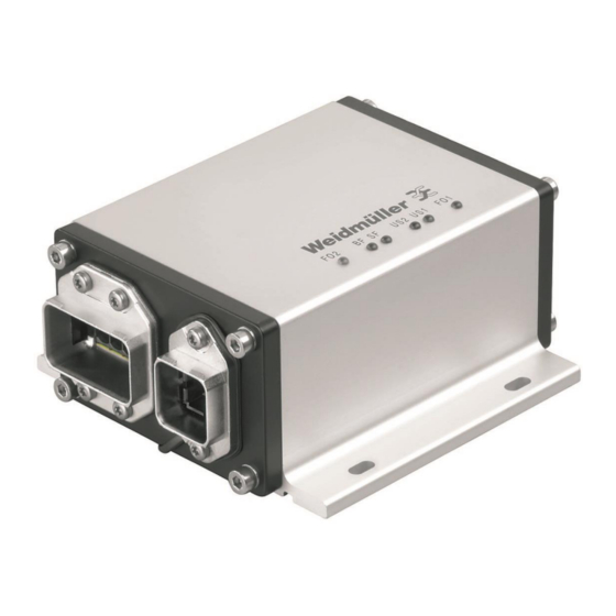
Foreword Foreword The FreeCon Active PROFINET-POF-Repeater from Weidmüller is a repeater for PROFINET IRT industrial use. It provides extended fibre-optic diagnostic capabilities in addition to its repeat and refresh functionality. The FreeCon Active’s tough IP65 metal housing is perfectly suited for harsh robotics applications. Revision history Version Date... -
Page 4: Table Of Contents
Contents Contents Foreword ..........................3 Revision history ........................3 Contact address ........................3 Copyright notice ........................3 Contents ..........................4 Safety Notices ....................... 6 Proper and intended use ..................6 Qualified staff ......................6 Accuracy of the technical documentation ..............6 CE label ........................ - Page 5 Contents Extended Diagnostic Capabilities ..............19 PLC diagnostics ....................19 Web browser diagnostics ..................23 Status and Maintenance ..................24 LED indicators ....................... 24 Technical Specifications ..................26 Warranty....................... 28 Appendix A: Pin assignments for data and power port ..........29 1253240000/00/02.11...
-
Page 6: Safety Notices
Safety Notices Safety Notices Proper and intended use NOTE This device is intended for use in applications as described in the operating instructions only. Any other form of usage is not permitted and can lead to accidents or destruction of the device. Using the products in non-approved applications will lead immediately to the expiration of all guarantee and warranty claims on the part of the operator against the manufacturer. -
Page 7: Recycling In Accordance With Weee
Safety Notices Recycling in accordance with WEEE B-to-B disposal Dear Weidmüller Customer, Purchasing our product gives you the opportunity to return the device to Weidmüller at the end of its service life. The EU Directive 2002/ 96 EC (WEEE) regulates the return and recycling of waste electrical and electronics equipment. -
Page 8: Overview Of The Freecon Active Repeater
Overview of the FreeCon Active PROFINET-POF-Repeater Overview of the FreeCon Active PROFINET-POF-Repeater The FreeCon Active PROFINET-POF-Repeater is used to refresh the fibre-optic signal over long industrial fibre optic paths. The additional diagnostic functions enable it to also monitor the fibre-optic lines used for in- dustrial and robotics applications. -
Page 9: Electrical Characteristics
Overview of the FreeCon Active PROFINET-POF-Repeater Electrical characteristics The FreeCon Active PROFINET-POF-Repeater uses a typical input current between 150 mA to 200 mA. It operates with an input voltage ranging from 18 to 30 VDC and a temperature range between -20 to 55 °C. The maximum power must not exceed 24 V and 16 A on either US1 or US2 at 40 °C (see chapter 3.2 power connection). -
Page 10: Installation And Connectors
Installation and Connectors Installation and Connectors Mounting Refer to the illustrations below for the actual mounting dimensions. Four screws must be used to mount the FreeCon Active PROFINET-POF-Repeater to a wall. Use the device itself as a guide to mark the proper lo- cations for the four screws. -
Page 11: Power Connection
Installation and Connectors Power connection WARNING Safety First! Calculate the maximum possible current in each power wire and common wire. Ob- serve all electrical codes dictating the maximum current allowable for each wire size. If the current goes above the maximum ratings, the wiring could overheat, causing serious damage to your equipment. -
Page 12: Data Connection
Installation and Connectors Data connection The FreeCon Active PROFINET-POF-Repeater has two 100BaseFX Ethernet ports for polymer optical fibre (POF). These SC-type fibre ports are fairly straightforward to connect since optical-fibre connections do not require the circuit needed for electrical signals. One of the optical lines is used to transmit data from device I to device II, and the other optical line is used transmit data from device II to device I, for full-duplex transmission. -
Page 13: Setup And Network Configuration
Setup and Network Configuration Setup and Network Configuration The FreeCon Active PROFINET-POF-Repeater can be configured and integrated into your system using ei- ther of the two available access methods: controller setup with GSDML file or Weidmüller FreeCon CFG ac- cess. Once a proper IP address has been assigned, you can also access and configure the device using a web browser. -
Page 14: Setup With Weidmüller Freecon Cfg
Setup and Network Configuration Setup with Weidmüller FreeCon CFG The software utility “FreeCon CFG” can also be used to configure the FreeCon Active PROFINET-POF- Repeater. This software – which can be downloaded free from the Weidmüller website – scans the Ethernet and displays any FreeCon Active PROFINET-POF-Repeater that it finds. - Page 15 Setup and Network Configuration Figure 9 Configuring a new IP address in FreeCon CFG 1253240000/00/02.11...
-
Page 16: Using A Web Browser To Access The Repeater
Setup and Network Configuration Using a web browser to access the device After the FreeCon Active PROFINET-POF-Repeater has been configured using FreeCon CFG, the web server hosted on the repeater can be accessed using the assigned IP address. Use a web browser installed on a PC that is on the same subnet. -
Page 17: Snmp Configuration
Setup and Network Configuration The FreeCon Active PROFINET-POF-Repeater must be power cycled after clicking on the STORE CON- FIGURATION button. The changes will then take effect after the reboot. SNMP configuration The FreeCon Active PROFINET-POF-Repeater supports the Simple Network Management Protocol (SNMP) in compliance with the PROFINET standard and supports MIB-2. - Page 18 Setup and Network Configuration Figure 12 Transferring the firmware file with FTP Use the command “ftp IP-address” to establish the FTP-connection to the repeater and confirm the user log- in with Enter. The confirmation “user logged in” appears. With the command “put filename” you can transfer the new firmware to the device. Note The transfer of the firmware needs only a few seconds, then follows a check and the update of the repeater, which needs up to 2 minutes.
-
Page 19: Extended Diagnostic Capabilities
Extended Diagnostic Capabilities Extended Diagnostic Capabilities The FreeCon Active PROFINET-POF-Repeater measures and reports the temperature, voltage supply, opti- cal amplitude margin and power budget. These values are normally accessed through the controller software (Step 7). They can also be accessed directly by connecting to the FreeCon Active PROFINET-POF- Repeater’s web server. - Page 20 Extended Diagnostic Capabilities Figure 14 Projecting PROFINET devices The next step ist to set the IP-address and device names, to make them addressable in the PROFINET network. Figure 15 Setting IP-addresses 1253240000/00/02.11...
- Page 21 Extended Diagnostic Capabilities Via the properties window you get to the input mask of the device name: Figure 16 Properties window for adapting the device name Figure 17 Setting device name 1253240000/00/02.11...
- Page 22 Extended Diagnostic Capabilities Figure 18 Assigning device name Now load the project into the PLC and switch it to the run-mode. If the PROFINET network is well configured, the two LEDs SF and BF will be switched off. You can see the diagnostic information of each part in the module information window (Step 7). Figure 19 Step 7 Configurations 1253240000/00/02.11...
-
Page 23: Web Browser Diagnostics
Extended Diagnostic Capabilities Web browser diagnostics You can connect to the web server on the FreeCon Active PROFINET-POF-Repeater to access the diagnos- tic measurements; simply enter the FreeCon Active PROFINET-POF-Repeater’s assigned IP address in your browser window and navigate to the diagnostics page. The following diagnostics screen will be shown: Figure 20 Browser-based diagnostics view Temperature... -
Page 24: Status And Maintenance
Status and Maintenance Status and Maintenance LED indicators There are six LEDs visible on the top of the device; the function of each is described in the tables below. Figure 21 The six LEDs on the FreeCon Active PROFINET-POF-Repeater 6.1.1 The FO1 and FO2 LEDs These two LEDs show the status of the fibre-optic transmission lines on ports 1 (FO1) and 2 (FO2). - Page 25 Status and Maintenance 6.1.3 The SF LED This LED is used to indicate a system failure or error. Colour Status Indicates On (solid) One or more of the following errors: - FO-transceiver not okay, - Configuration error, - Station name has not been assigned, - IP number has not been assigned, - No connection to I/O controller, - Power margin below 2 dB.
-
Page 26: Technical Specifications
Technical Specifications Technical Specifications Technology standards 100BaseFX POF Fast Ethernet, PROFINET IRT Fibre interface Two 100BaseFX POF ports (PROFINET PushPull V14 connector, POF) 100BaseFX Optical Fibre (POF) Wavelength 650 nm Max. TX -2 dBm Min. TX -8.5 dBm Min. RX sensitivity -23 dBm Link Budget 15 dB... - Page 27 Technical Specifications Regulatory Approvals Safety UL 1863 Emissions EN 61000-6-4 Class A EN61000-4-2 Level 3 EN61000-4-3 Level 3 Burst EN61000-4-4 Level 3 Surge EN61000-4-5 Level 3 CRFI EN61000-4-6 Level 3 Shock IEC 60068-2-27 Hammer IEC 60068-2-75 Vibration IEC 60068-2-6 1253240000/00/02.11...
-
Page 28: Warranty
Warranty Warranty Weidmüller grants a warranty on this product in accordance with the warranty terms as described in the gen- eral conditions of sale of the Weidmüller company which has sold the products to you. Weidmüller warrants to you that such product defects of which have already existed at the time of delivery will be repaired by Weidmüller free of charge or that Weidmüller will provide a new, functionally equivalent product to replace the defective one. -
Page 29: Appendix A: Pin Assignments For Data And Power Port
Appendix A Appendix A: Pin assignments for data and power port Data port Power port Pin assignments US1+ US1- US2+ US2- 1253240000/00/02.11...
Need help?
Do you have a question about the FreeCon Active IE-CDR-V14MSCPOF/VAPM-C and is the answer not in the manual?
Questions and answers