Table of Contents

Subscribe to Our Youtube Channel
Related Manuals for TriCom TCR-HHR-02

Summary of Contents for TriCom TCR-HHR-02
- Page 1 OPERATOR'S MANUAL TCR-HHR-02 TACTICAL REPEATER/COMMUNICATIONS SYSTEM DOCUMENT # 90400-01223 Tricom Research, Inc. • http://www.tricomresearch.com 17981 Sky Park Circle, Suite M, Irvine, CA 92614 Ph: (949) 250-6024 fax: (949) 250-6023...
- Page 2 Revision History - Document 90400-01223 Revision Description Date Preliminary Release 20 Sep 2013 17 OCT 2016 Updated 148 Radio portions Note: The latest version of this manual can be downloaded from our website at http://www.tricomresearch.com/downloads.html.
-
Page 3: Table Of Contents
TABLE OF CONTENTS Abbreviations and Glossary ................iv Safety Summary .....................v CHAPTER 1 GENERAL INFORMATION AND SAFETY INSTRUCTIONS INTRODUCTION ..................1 Safety Precautions ..................1 Physical Description ..................1 Specifications ....................2 Equipment Provided..................2 Controls and Indicators ..................3 Controls and Indicators ..................3 CHAPTER 2 OPERATING INSTRUCTIONS INTRODUCTION ..................7 System Setup for Repeater Operation ............7 Setup for Communications System Operation ..........14... - Page 4 Figure 2-8 Egress panel vent ..................9 Figure 2-9 FAN enclosure vent .................9 Figure 2-10 TCR-HHR-02 Repeater System Signal Flow Block Diagram ....11 Figure 2-11 TCR-HHR-02 Communications System Signal Flow Block Diagram ..12 Figure 2-12 Typical Tactical Repeater Setup ..............13 Figure 2-13 External DC Power Cable ................15...
-
Page 5: Abbreviations And Glossary
ABBREVIATIONS AND GLOSSARY Automatic gain control Automatic level control Amplitude modulation Antenna ANW2 Advanced Networking Wideband Waveform Bits per second Cipher text Continuous wave COMSEC Communications security Decibel Decibel referenced to 1 milliwatt (0 dBm = 1 mW) Frequency modulation Hertz Integrated Waveform JITC... -
Page 6: Safety Summary
The following are general safety precautions that are not related to specific procedures. These precautions do not appear elsewhere in this manual. You must read and understand these precautions before replacing, disassembling, or performing maintenance on the TCR-HHR-02 Tactical Repeater System. -
Page 7: General Information And Safety Instructions
This manual contains important safety and operating instructions for the TCR-HHR-02, review the Safety Summary at the beginning of this Technical Manual. Use of an attachment not recommended or sold by Tricom Research may result in risk of fire, electric shock, or personal injury. -
Page 8: Specifications
Thermo Plastic Storm Case Refer to TCR-MBA-50 WB Operator’s Manual for detail information on the specifications of the Power Amplifier. 1.4. Equipment Provided. The TCR-HHR-02 system ships with the components listed in Table 1-2. Table 1-2 TCR-HHR-02 Packing List Equipment Quantity... -
Page 9: Controls And Indicators
1.5. Controls and Indicators. Figure 1-1 TCR-HHR-02 Egress Panel Table 1-3 TCR-HHR-02 Egress Panel RAD2-WB Antenna Port RAD1 Antenna Port AC Power Jack (115/230 VAC) Vent DC Input Power Jack (12/24 VDC) PA Remote (Mini USB Jack) RAD2-LOS Antenna Port... -
Page 10: Table 1-4 Tcr-Hhr-02 Power Amplifier Controls And Indicators
Table 1-4 TCR-HHR-02 Power Amplifier Controls and Indicators 1 LOS Mode Select Button (toggles Transmit LED Indicator between FM, AM, SINCGARS, HAVE QUICK, WB and WB FH LOS modes) 2 Power ON/OFF, RF Power Level and Fault LED Indicator LED Brightness Adjust Button... -
Page 11: Table 1-5 Tcr-Hhr-02 System Components
RAD1 Audio Cable 6 BAT2 Charger and Battery AC-DC Power Supply 7 Radio Mount Locking Pin Figure 1-4 TCR-HHR-02 Controls and Indicators Table 1-6. TCR-HHR-02 Controls and Indicators 1 Power ON/OFF Button BAT1 Cell B Status LED Indicator 2 System ON LED Indicator... -
Page 12: Table 1-7 Tcr-Hhr-02 Power Control Module Indication Matrix
Table 1-7. TCR-HHR-02 Power Control Module Indication Matrix INDICATOR ON OR FLASHING GREEN FLASHING RED SYSTEM IS OFF SYSTEM ON NO AC OR EXT DC EXT DC AC POWER OR EXT 12-32 NO AC POWER OR EXT DC <12 APPLIED VDC APPLIED VDC OR EXT DC >... -
Page 13: Operating Instructions
2.1. System Setup for Repeater Operation. Refer to Figures 2-8 and 2-9 for a system block diagram of the TCR-HHR-02 in repeater configuration. 2.1.1 Install two BB-2590 batteries and secure the battery chargers to the batteries using the Velcro strap as illustrated in Figure 2-1. -
Page 14: Figure 2-3 Rad1 Installed With Retransmission Cable Connected
2.1.4 Move the radio mounting bracket to the vertical position, install RAD1 first and connect one side of the retransmit cable (see Figure 2-3). RAD1 installed in vertical position and retransmission cable connected Figure 2-3 RAD1 installed with retransmission cable connected 2.1.5 Install RAD2 and connect the other end of the retransmission cable (see Figure 2-4. -
Page 15: Figure 2-7 Radio Mount In Horizontal Position And Locking Pin In Locked Position
2.1.7 Turn on the system by pressing the power ON button (see Figure 1-4, DC and battery power status LEDs will flash sequentially and fans will turn on for 5 seconds). 2.1.8 Move the radio mounting bracket to the horizontal position (see Figure 1-3) and ensure the locking pin is engaged in the locked position (see Figure 2-6). - Page 16 2.1.14 Select LOS mode of operation and the appropriate RF power level (25 or 50 watts power source dependent) on the TCR-MBA-50 WB power amplifier (refer to the TCR-MBA-50 WB Operator’s Manual for information on how to setup the power amplifier for LOS operation).
-
Page 17: Figure 2-10 Tcr-Hhr-02 Repeater System Signal Flow Block Diagram
DC POWER CONTROL RAD1 RAD2 Figure 2-10 TCR-HHR-02 Repeater System Signal Flow Block Diagram... -
Page 18: Figure 2-11 Tcr-Hhr-02 Communications System Signal Flow Block Diagram
Figure 2-11 TCR-HHR-02 Communications System Signal Flow Block Diagram... -
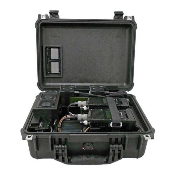
Page 19: Figure 2-12 Typical Tactical Repeater Setup
Antenna Antenna Figure 2-12 Typical Tactical Repeater Setup... -
Page 20: Setup For Communications System Operation
Setup for Tactical Communications System mode is the same as the setup for the repeater mode except that the retransmission cable is not used. Refer to Figure 2-11 for the signal flow diagram of the TCR-HHR-02 in dual hand held radio communications system mode. 2.3. Operation of Power Control. -
Page 21: Table 2-1 External Dc Power Cable Pinout
Black DC Ground 2.3.4 Battery Power Operation – The battery chargers on the TCR-HHR-02 are only compatible with BB-2590 Li-Ion batteries. To ensure a reliable power backup is available during repeater or communications system operation, apply an external power source (AC or 24 VDC) prior to use to charge the onboard batteries. - Page 22 2.3.5 Battery Charger Operation – It is recommended that the batteries be charged prior to repeater or communications system operation to reduce system heat generation. Once the batteries are fully charged the battery chargers will be in standby mode and will not generate any significant amount of heat.
-
Page 23: Maintenance And Warranty Information
Hook up a watt meter in line with the external antenna port under test (SAT, LOS or WB). b. Turn the TCR-HHR-02 and watt meter on and place the watt meter in FWD power. Setup RAD2 for 3 watts, FM at 300 MHz and the PA for the appropriate mode under test (LOS, SAT, WB) key up RAD2 and verify that the watt meter reads the power level specified in Table 3-1. -
Page 24: Corrective Maintenance
Turn off and disconnect the watt meter and return TCR-HHR-02 to normal configuration. If the TCR-HHR-02 power out test fails, please follow the troubleshooting guide provided in Operator’s Manual for the TCR-MBA-50 WB. If the fault is still present after following the troubleshooting procedure for no/low RF out use corrective maintenance to repair the issue. -
Page 25: Basic Troubleshooting Procedures
3.4. Warranty Maintenance. WARRANTY STATEMENT Tricom Research warrants to its customers that the products it manufactures and sells will be free from defects in materials and workmanship for a period of one (1) year. This warranty shall not apply to any defect, failure, or damage caused by improper use or inadequate maintenance and care. -
Page 26: Contact Information
3.5. Contact Information. Please call (949) 250-6024 to obtain an RMA number prior to returning any failed unit(s): Tricom Research, Inc. 17981 Sky Park Circle Suite M Irvine, California 92614 Phone: (949) 250-6024 Fax: (949) 250-6023 Email: info@Tricomresearch.com www.Tricomresearch.com RMA requests may be submitted on-line at:...
Need help?
Do you have a question about the TCR-HHR-02 and is the answer not in the manual?
Questions and answers