
Subscribe to Our Youtube Channel
Related Manuals for Aalborg TIO

Summary of Contents for Aalborg TIO
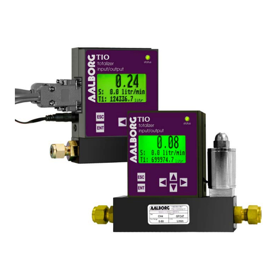
- Page 1 Technical Data Sheet No.: TD-TIO-0911 Rev B Date of Issue: September 2011 QUALITY SYSTEM REGISTERED OPERATING MANUAL Totalizer-Input/Output Flow Monitor/Controller...
- Page 2 Aalborg7 is a registered trademark of Aalborg7 Instruments & Controls. NOTE: Aalborg7 reserves the right to change designs and dimensions at its sole discretion at any time without notice. For certified dimensions please contact Aalborg7.
-
Page 3: Table Of Contents
Submenu “Diagnostic Menu” “Event Register Menu”........... INSTALLATION................General Directions..................... Hardware Installation.................... 6.2.1 Connecting TIO to GFM series flow meter............6.2.2 Connecting TIO to GFC series flow controller............6.2.3 Connecting TIO to flow meters / controllers from other manufacturers (stand alone)...................... - Page 4 TROUBLESHOOTING..............Common Conditions................... Troubleshooting Guide..................APPENDIX A TIO Totalizer Input/Output Flow Monitor/Controller EEPROM Variables APPENDIX B Internal K-Factors Table APPENDIX C Totalizer-IO ASCII Commands Set APPENDIX D Mechanical Drawings APPENDIX E Circuit Layout Diagrams APPENDIX F Warranty...
-
Page 5: Unpacking The Tio Totalizer
UNPACKING THE TIO TOTALIZER Inspect Package for External Damage Your TIO Totalizer-Input/Output Flow Monitor/Controller was carefully packed in a sturdy cardboard carton with anti-static cushioning materials to withstand ship- ping shock. Upon receipt, inspect the package for possible external damage. In case of external damage to the package, contact the shipping company immedi- ately. -
Page 6: Safety Instructions / Introduction
Some of the IC devices used in the TIO are static-sensitive and may be damaged by improper handling. When adjusting or servicing the device, use of a grounded wrist strap is recommended to prevent inadvertent damage to the integral solid-state circuitry. -
Page 7: Specifications
SPECIFICATIONS ADC/DAC RESOLUTION: 12 bit. ACCURACY: ±0.1% F.S. ANALOG INPUTS: 0-5 Vdc, 4-20 mA, 5-10 Vdc (jumper-selectable), 0-10 Vdc (special order). ANALOG OUTPUTS: 0-5 Vdc, 4-20 mA (jumper-selectable), 0-10Vdc (special order). LCD: 128x64 graphic LCD with instantaneous Flow reading and Total volume indication. Adjustable LCD contrast and back light. - Page 8 INTERFACE CONNECTORS: Process I/O signals and digital RS-232/RS-485 interface: miniature 9 pin female D-SUB connector. Digital optically-isolated outputs: TERMINAL BLOCK HEADER 4POS 3.5MM male pins, Shrouded (Mated connector: Tyco Electronics P/N: 284510-4). ENVIRONMENT: Installation Level II; Pollution Degree II. ELECTROMAGNETIC COMPATIBILITY: Compliant ref.
-
Page 9: Electrical Connections
Communication reference Optional) Communication (RS-232 – output, RS-485 – RS232 TX, Optional RS485 (-) input/output) Analog Input/Output reference (common for pins 4 and 5) +5Vdc reference input (for 5-10 Vdc interface only) Figure 4.1 - TIO 9 PIN "D" CONNECTOR CONFIGURATION... -
Page 10: Power Supply Connections
TIO via miniature 9 pin female D-SUB connector. Power Supply Connections The power supply requirements for TIO are: 12 to 26 Vdc, (unipolar power sup- ply). DC Power (+) --------------- pin 2 of the 9 pin "D" connector DC Power (-) --------------- pin 1 of the 9 pin "D"... -
Page 11: Set Point (Sp) Output Signal Connections
PV input (-) --------------- pin 8 of the 9 pin “D” connector. Set Point (SP) Output Signal Connections Set Point (SP) output signal connection is required only if TIO is mated to the flow controller and will be used as a source for a Set Point control signal. -
Page 12: Digital Communication Interface Connections
CAUTION: When connecting the load to the output terminals always check actual jumper J2 configuration. Do not exceed the rated values shown in the specifications (see Table 4.2). Failure to do so might cause damage to this device. Be sure to check if the wiring and the polarity of the power supply and SP signals are correct before turning the power ON. - Page 13 RS-232 Communication Interface Connection: Crossover connection must be established: RS-232 RX (pin 2 on the host PC DB9 connector)------pin 7 of the 9 pin "D" connector (TX-) RS-232 TX (pin 3 on the host PC DB9 connector)------pin 3 of the 9 pin "D" connector (RX+) RS-232 SIGNAL GND (pin 5 on the host PC DB9 connector)------pin 6 of the 9 pin "D"...
-
Page 15: Digital And Pulse Optically-Isolated Output Connections
When the TIO device is set as the last device on the RS-485 bus segment and 220 Ohm bus termination is required, set the jumper J2G to position 19-20. This will result in connection 220 Ohm resistor between RS-485 (+) and (-) terminals. - Page 16 WARNING: Optically-isolated outputs have maximum absolute voltage rating 250 Vdc RMS. Do not exceed maximum allowed limits for voltage. Doing so may cause personal injury or damage to this device.
-
Page 17: Lcd Key-Pad Operation: Data Entry And Configuration
Interface: RS-232 Baud Rate: 9600 RS485 address: 11 Figure 5.1: TIO Firmware and Communication Interface Info Screen NOTE: Actual content of the LCD screen may vary depending on the model and device configuration. Based on device configuration (Device Function as flow meter or flow controller), different parameters may be displayed in the Process Information (PI) screen by pressing the UP or DN pushbuttons. - Page 18 99.97 litr/min 1589324.5 litr Figure 5.2: TIO Initial PI Screen (Device Function: Flow Meter) 99.97 S: 100.0 litr/min 1589324.5 litr Figure 5.3: TIO Initial PI Screen (Device Function: Flow Controller NOTE: Actual content of the LCD screen may vary depending on the...
-
Page 19: Set Point Control (Only For Devices Set As Controller)
Set Point Control (only for devices set as controller) When TIO is configured as controller it can be used to control set point value for mated flow controller using analog output interface. NOTE: Your TIO device input / output jumpers were factory configured according to your order. - Page 20 The Set Point value can be adjusted locally using LCD/keypad, remotely via RS- 232/RS-485 digital interface or can be programmed in advance using user-preset programs of up to sixteen steps (Program Set Point Mode). a) Adjusting Set Point value using local LCD/keypad Current Set Point value is displayed on the second line of the main PI screen, next to the ‘S’...
-
Page 21: Menu Structure
NOTE: Before executing, the program should be entered in the program table (see Paragraph 5.3.16) Current flow rate value 51.01 litr/min Current step time Current SP value S 51.0 0.0s elapsed CS: 1 0.0 Current program step M:D L:Off S: Off Program Mode: E/D Program Loop Mode: On/Off Program Run Status: On/Off... -
Page 22: Parameter Entry
Figure 5.5 Pressing the UP or DN button to select the Disabled option and then the ENT but- ton to save settings will disable program protection. If PP password is set to any value more than Zero, the firmware will prompt with “Enter PP Password”... -
Page 23: Submenu "Change Pp Password
NOTE: During data entry the input vales are checked for acceptability. If data is not acceptable, it is rejected and a message is generated indicating that the new data has not been accepted. If the menu with tabular entry is selected, the available menu options can be set with the UP and DN buttons and are accepted by pressing the ENT button. -
Page 25: Submenu "Device Information
Once “Change PP Password” menu is selected, the following screen will appear: Figure 5.8 In order to protect device configuration parameters when changing the PP pass- word, the old PP password must be entered. NOTE: By default the device is shipped from the factory with Program Protection (PP) password set to Zero (PP Disabled). -
Page 26: Submenu "Measuring Units
Figure 5.10 5.3.3 Submenu “Measuring Units” Use the “Engineering Units and K-Factor Menu” to navigate to “Measuring Units” menu option. This option allows configuration of the flow meter/controller with the desired units of measurement. These are global settings and determine what appears on all process information screens and data log records. - Page 27 The following selections are available: 1 second, 60 seconds (1 minute), 3600 sec- onds (1 Hour), 86400 seconds (1 Day). The default entry is 60 seconds. If a mass- based User-defined Unit is desired, the “UD Unit Use Density” parameter must be set to “YES”.
- Page 28 FLOW RATE TOTALIZER NUMBER DESCRIPTION ENGINEERING ENGINEERING UNITS UNITS kg/hr Kilograms per hour kg/day Kilograms per day lb/sec Pounds per second lb/min Pounds per minute lb/hr Pounds per hour lb/day Pounds per day Mton/min Mton Metric Ton per minute Mton/hr Mton Metric Ton per hour Igal/sec...
-
Page 29: Submenu "K-Factors Settings
Depending on the TIO function configuration (flow meter or controller) there are two Alarm algorithms. If the TIO is configured as a flow meter, Flow Alarm condi- tions become true when the current flow reading is equal to or Higher/Lower than corresponding values of High and Low Flow Alarm levels. - Page 30 a) Flow Alarm Mode (Tabular entry) This function determines whether the Flow Alarm is Enabled or Disabled. The following selections are available: Enabled or Disabled. The default entry is Disabled. Alarm Mode selections can be set with the UP and DN buttons and are accepted by pressing ENT button.
-
Page 31: Submenu "Totalizer #1
5.3.7 Submenu “Totalizer #1” TIO provides the user with two independent Programmable Flow Totalizers. The total volume of the flowing fluid is calculated by integrating the actual instanta- neous fluid flow rate with respect to time. Totalizer #1 (main Totalizer) value is stored in the EEPROM and saved every 1 second. - Page 32 NOTE: Before enabling the Totalizer, ensure that all Totalizer settings are configured properly. Totalizer Start values must be entered in the currently active Volumetric or Mass flow engineering unit. The Totalizer will not totalize until the Process Flow Rate becomes equal to or more than the Totalizer Start value.
-
Page 33: Submenu "Totalizer #2
The default entry is Disabled. Totalizer #1 Auto Reset selections can be set with the UP and DN buttons and are accepted by pressing the ENT button. f) Totalizer #1 Auto Reset Delay (Numerical entry) This option may be desirable when the “Totalizer #1 Auto Reset” feature is enabled. - Page 34 NOTE: Before enabling the Totalizer, ensure that all Totalizer settings are configured properly. Totalizer Start values must be entered in currently active Volumetric or Mass Flow engineering units. The Totalizer will not totalize until the process flow rate becomes equal to or more than the Totalizer Start value.
- Page 35 e) Totalizer #2 Power On Delay (Numerical entry) Sometimes it is convenient to start the Totalizer only after a specified power-up delay interval. Most of the mass flow meters and controllers require some warm-up time from the power-up event in order to stabilize process variable output and to get accurate reading.
-
Page 36: Submenu "Pulse Output
5.3.9 Submenu “Pulse Output” The flow Pulse Output is operates independently from Totalizers and is based on configuration settings (see Figure 5.7) which can provide pulse frequency pro- portional to instantaneous fluid flow rate. The LCD/keypad and digital communication interface commands are provided to: •... -
Page 37: Submenu "Opt. Outputs Settings
5.3.10 Submenu “Opt. Outputs Settings” Two sets of optically-isolated digital outputs are provided to actuate user-sup- plied equipment. These are programmable via digital interface or LCD/Keypad such that the outputs can be made to switch when a specified event occurs (e.g. when a Low or High Flow Alarm limit is exceeded, when the Totalizer reaches a specified value), or it may be directly controlled by user. -
Page 38: Submenu "Display Settings
5.3.11 Submenu “Display Settings” Process Information screens can be configured to be static (manual control) or dynamic (automatic sequencing). In the static mode pressing the UP button allows the user to page through the PI screens in the forward direction. Pressing DN button, pages through the PI screens in the reverse direction. -
Page 39: Submenu "Device Function
This menu selection allows the selection of TIO function according to the mated device type. If TIO is connected to flow meter then “Meter” function must be selected. If TIO is connected to flow controller then “Controller” function must be... -
Page 40: Submenu "Communication Settings
115200 By default the device shipped from factory with baud rate set to 9600. NOTE: The baud rate set on the TIO device should always follow the baud rate of the host PC or PLC it connected to. b) RS-485 Bus Address (Numerical entry) The standard TIO comes with an RS-232 interface. -
Page 41: Submenu "Device Calibration
Scale Range value set to 10.0 Litr/min and the device is configured for 0-5 Vdc analog input, when 5.0 Vdc is applied to TIO analog input the PI flow rate will indicate 100.0%FS (if %F.S. units of measure is selected). - Page 42 100% F.S.). The 0-5 (0-10)Vdc output has only scale variable and 4-20 mA output has offset and scale variables. Power up the TIO instrument for at least 15 minutes prior to commencing the calibration procedure. Observe analog output jumper position (see Figure 4.2) and connect the corresponding type of...
- Page 43 20 mA output has offset and scale variables. NOTE: Check the actual input jumpers’ configuration before applying any input signal to TIO. Be sure your input signal does not exceed the maximum allowed level for corresponding input type (see Table 4.1).
-
Page 44: Submenu "Signal Conditioner
5.3.15 Submenu “Signal Conditioner” A noise reduction filter algorithm (Running Average or Noise Reduction Filter) is available in the flow meter when pulsating flow or especially noisy signals are encountered. The Flow Linearizer algorithm is also available when flow linearity must be improved. - Page 45 The valid range for flow values is from 0.000000 to 1.000000 (note: TIO will accept up to 6 digits after decimal point). There are 11 elements in the table so the data should be obtained at an increment of 10.0 % of F.S.
-
Page 46: Submenu "Program Set Point
Note: It is recommended to use Aalborg7 supplied calibration and maintenance software for linearization table calibration. This software includes an automated calibration procedure which may radically simplify reading and writing for the EEPROM linearization table. 5.3.16 Submenu “Program Set Point” The Program Set Point Control allows execution of custom, user-preset pro- grams of up to sixteen steps. -
Page 47: Submenu "Event Register Menu
PSP Step settings in the device’s nonvolatile memory. 5.3.17 Submenu “Event Register Menu” TIO is equipped with a self-diagnostic Alarm Event Register which is available via the digital interface and on the screen LCD indication. Use the “Diagnostic Menu” to navigate to “Event Register Menu” option. - Page 48 The following Diagnostic Events are supported: Table 5.2 EVENT LCD BIT DIAGNOSTIC AND ALARM EVENTS DESCRIPTION NUMBER CODE CPU Temperature Too High High Flow Alarm Low Flow Alarm Range Between High and Low Totalizer#1 Exceed Set Event Volume Limit Totalizer#2 Exceed Set Event Volume Limit Optical Pulse Output Queue overflow Flow Rate above Limit Vcc Power Voltage Out of Range...
- Page 49 The following settings are available for “Event Register Menu” (see Figure 5.7): a) Event Register Status (Read Only) Each active Alarm Event will be indicated on the LCD screen. In addidtion the total number of currently active events will be displayed on the first line (header).
- Page 50 Events Latch Mask: 0-CPU Temp. High [*] 1-Hight Flow Alm. 2-Low Flow Alm. 3-Range b/w H-L 4-Tot#1> Limit In the example shown above, latch features for all events are disabled, except event #0. In order to change Event Latch mask settings, the user should select the desired event using UP and DN buttons and then press the RIGHT button.
-
Page 51: Submenu "Diagnostic Menu" "Event Register Menu
Reset Event Register (Tabular entry) The Event Register can be reset by selecting “Reset Event Register” menu option. A typical display with Reset Event Register screen is shown below. Reset Event Reg.: DO YOU WANT RESET EVENT REG? Once the “YES” option is selected, the Event Register will be reset and the following conformation screen will appear. - Page 52 Analog Output Value: Output Conf: 0-5 Vdc DAC Update: Enabled DAC Counts: 0 c) LCD Back Light Settings (Read Only) This menu selection provides information about LCD back light level, PWM duty cycle and contrast (read only). A typical display with LCD Back Light Settings screen is shown below.
-
Page 53: Installation
Personnel must read and understand this operating manual before performing any installation or configuration steps. • The TIO device should only be operated by trained personnel. All instructions in this manual are to be observed. • Ensure that power and all input / output signals are correctly wired according to the wiring diagram provided in this manual. -
Page 54: Connecting Tio To Gfm Series Flow Meter
6.2.1 Connecting TIO to GFM series Flow Meter a) Mounting Use GFM mounting kit (See Table 5.1) to attach TIO to the GFM Flow Meter (see Figure 6.1). Figure 6.1 Mounting TIO to the GFM Flow Meter b) Electrical Connection GFM Flow Meters have three different output interfaces (0-5, 5-10 Vdc, 4-20 mA) which can be used to provide flow input signal to TIO. - Page 58 TIO receiving the power from the GFM. c) Input/Output Jumper Configuration NOTE: Your TIO device input / output jumpers were configured at the factory according to your order. There is no need to change input / output jumpers’ configuration unless a different input is being used.
- Page 59 TABLE 6.2 J2 INPUT / OUTPUT JUMPER CONFIGURATION OPTIONS FOR GFM SERIES FLOW METERS J2 JUMPER CONFIGURATION PV INPUT TYPE NOTE CABLE KIT (TIO INPUT) KIT-TM-DD 0 - 5 Vdc 2 - 3 5 - 6 8 - 9 10-11 14-15 17-18 KIT-TM-FD...
-
Page 60: Connecting Tio To Gfc Series Flow Controller
6.2.2 Connecting TIO to GFC series flow controller a) Mounting Use GFC Mounting Kit (See Table 6.3) to attach TIO to the GFC flow controller (see Figure 5.5). Figure 6.5 Mounting TIO to the GFC Flow Controller b) Electrical Connection GFC flow controllers have two output interfaces: 0-5 Vdc and 4-20 mA which can be used to provide flow input signal to TIO. - Page 63 Based on interface being used and power supply option, optional Cables Kit Assemblies are available for order. See Table 6.3 for optional GFC Cables Kit Assemblies. TABLE 6.3 OPTIONAL GFC POWER SUPPLY / CABLES AND MOUNTING KIT ASSEMBLIES Kit Part Communication GFC Power Description...
- Page 64 240 Vac to 24 Vdc power 0-5 Vdc 24 Vdc only 240UK-4N supply GFC flow controller KIT-TC mounting kit, no cables, no power supply NOTE: All GFC Kits (except KIT-TC) have power supply for GFC flow controller and TIO receiving the power from GFC.
- Page 65 Input/Output Jumper Configuration NOTE: Your TIO device input / output jumpers were configured at the factory according to your order. There is no need to change the input / output jumper’s configuration unless different input is being used. Before applying power and process signals make sure the input / output jumpers are installed in the correct position (See Table 6.4).
- Page 66 When TIO is connected to flow meters / controllers from other manufactures, it can be used as stand-alone table top or panel- mounted (see Figure 6.8). On the back side of the TIO enclosure there are 4 tapped holes which are designated to be used for the panel-...
-
Page 67: Connecting Tio To Flow Meters / Controllers From Other Manufacturers (Stand Alone)
Figure 6.8 Dimensions for Panel Mounted Installation b) Electrical Connection TIO can be used with any generic flow meter / controller which supports 0-5 Vdc and / or 4-20 mA input / output interfaces. It also can be ordered for 0-10 Vdc input / output interface (special order not supported by generic models). - Page 70 Input/Output Jumper Configuration NOTE: Your TIO device input / output jumpers were configured at the factory according to your order. There is no need to change input / output jumper’s configuration unless different input is being used. Before applying power and process signals, make sure the input /out put jumpers are installed in the correct position (See Table 6.5).
- Page 71 Parameters configuration Following parameters must be configured: • Device Function (See 5.3.12 Submenu “Device Function”). If TIO is connected to flow controller, then “Controller” function must be selected. If TIO is connected to flow meter, then “Meter” function must be selected.
- Page 72 Troubleshooting Guide INDICATION LIKELY REASON SOLUTION LCD Display remains Power supply is bad or Measure voltage on pins 2 and 1 of the DB9 blank when unit is polarity is reversed. interface terminal connector. If voltage is powered up. Status LED out of specified range, then replace power is OFF supply with a new one.
- Page 73 Wrong host PC inter- Make sure interface type (RS-232 or RS- ing, but communication face, or wiring connec- 485) on the host PC is the same as on TIO interface does not work. tion. device. If required, use RS-232 to RS-485 converter.
- Page 74 APPENDIX A TIO Totalizer Input/Output Flow Monitor/Controller EEPROM Variables Rev.A001 [08/10/2011] INDEX NAME DATA TYPE NOTES BlankEEPROM[10] Do not modify. Table Revision [PROTECTED] char[10] SerialNumber[20] Serial Number [PROTECTED] char[20] ModelNumber[20] Model Number [PROTECTED] char[20] SoftwareVer[10] Firmware Version [PROTECTED] char[10] ManufReservedF1...
- Page 75 INDEX NAME DATA TYPE NOTES SetPointPFS Set Point value in %FS fraction notation [0.0 - 1.1] float DiagEventLatchMask Diagnostic Events Latch Mask register: Clear bit-> mask uint Reserved3 Device General Reserved Settings float Reserved4 Device General Reserved Settings float OptOut1_Config Optical Output #1 Configuration (function) uint OptOut2_Config...
- Page 76 INDEX NAME DATA TYPE NOTES Totalizer#1 backup volume in %s (saved every 6 Total1_Volume_BkUp float minutes) Reset Total. Volume value when Totalizer value Total1_AutoReset uint equals Limit volume 0 - No, 1 - Yes Delay in seconds before AutoReset will reset Total1_AtoResetDelay uint Totalizer#1 volume reading to zero [0-3600]...
- Page 77 INDEX NAME DATA TYPE NOTES FlowTbl[3]. FlowPFSOut Flow Linearizer Index 3 PFS Out [0.0 – 1.0] float FlowTbl[4]. FlowPFSIn Flow Linearizer Index 4 PFS In [0.0 – 1.0] float FlowTbl[4]. FlowPFSOut Flow Linearizer Index 4 PFS Out [0.0 – 1.0] float FlowTbl[5].
- Page 78 INDEX NAME DATA TYPE NOTES PSPTbl[5].Time PSP Table Index 5 Time (sec) float PSPTbl[6].PFS PSP Table Index 6 Set Point PFS (0.0-1.0) float PSPTbl[6].Time PSP Table Index 6 Time (sec) float PSPTbl[7].PFS PSP Table Index 7 Set Point PFS (0.0-1.0) float PSPTbl[7].Time PSP Table Index 7 Time (sec)
- Page 79 APPENDIX B Internal K-Factors Table K Factor DENSITY INDEX ACTUAL GAS Relative [Cal/g] [g/I] to N Argon Ar 1.4573 .1244 1.782 Arsine AsH3 0.6735 0.1167 3.478 Boron Triflouride BF3 0.5082 0.1778 3.025 Bromine Br2 0.8083 0.0539 7.130 Acetylene C2H2 0.5829 0.4036 1.162 Cyanogen C2N2...
- Page 80 APPENDIX C Totalizer-IO ASCII Commands Set RS232/RS485 Rev. A1 07/18/2011 The standard Totalizer-IO comes with an RS232 interface. The protocol described below allows communication with the unit using either a custom software pro- gram or a “dumb” terminal. All values are sent as printable ASCII characters. For RS-232 interface, the start character and two characters of address must be omit- ted.
- Page 94 UART ERROR CODES Not Supported Command or Back Door is not enabled. Wrong # of Arguments. Address is Out of Range (MR or MW commands). Wrong # of the characters in the Argument. Attempt to Alter Write Protected Area in the EEPROM. Proper Command or Argument is not found.
- Page 95 APPENDIX D Mechanical Drawings...
- Page 96 APPENDIX E Circuit Layout Diagrams Circuit Layout Top...
- Page 97 Circuit Layout Bottom Mirror...
- Page 98 It is assumed that equipment selected by the customer is con- structed of materials compatible with the environment in which the TIO is being used. Proper selection is the responsibility of the customer. It is...
Need help?
Do you have a question about the TIO and is the answer not in the manual?
Questions and answers