Advertisement
Quick Links
Advertisement

Summary of Contents for dtm KEYPOINT
- Page 1 WIRELESS CODE KEYPAD assembly and operating manual v.1.1...
-
Page 3: General Information
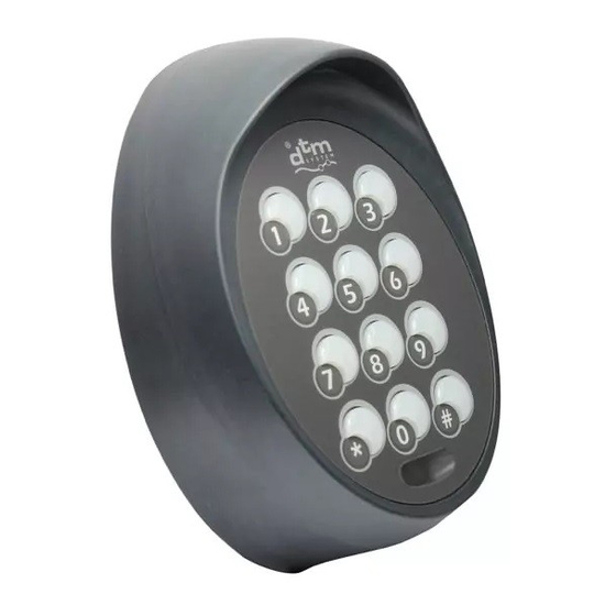
1. General information The KEYPOINT wireless code keypad is a battery-powered radio transmitter. It has 255 control channels operating at the frequency of 868MHz and 4 control channels operating at the frequency of 433MHz. Sends a radio signal after entering the correct code. The keyboard is equipped with a light sensor and a proximity sensor. - Page 4 3. Assembly The keyboard is delivered with batteries packed individually, not placed in the device. The batteries should be placed in the battery basket on the electronics board inside the housing (see section 11.2 Battery replacement). Before installing the device, check the radio range of the keypad.
- Page 5 keyboard panel proximity slide and lighting the keyboard sensor into the bracket mounting bracket attach the bracket torx screw screw the torx housing cover attach the cover Fig.1. Construction and assembly of the keyboard.
- Page 6 4. Using the keyboard The control consists in entering the individual channel code on the keyboard and confirming it with the button marked # or entering the universal code, and then pressing the button marked * and entering the channel number and confirming it with the # button.
- Page 7 5.Keyboard programming Keyboard programming The keyboard is programmed by entering codes on the device panel. All commands are preceded by the administrator code. The administrator code consists of 4 digits. The factory default admin code is 1111. 5.1. Changing the administrator code To change the administrator code, enter on the device panel: *old_code#*new_code#...
- Page 8 Adding or changing an individual code for a channel: *administrator_code#channel_number#n_channel_c ode# Example: Setting code 4321 for 3rd channel of DTM868MHz system *1234#3#4321# Setting code 5678 for 2nd channel of DTM433MHz system *1234#402#5678# 5.3. Deleting an individual channel code Channel code deleting: *administrator_code#channel_number#* Example: Deleting an indivdual code of 3rd channel of...
- Page 9 5.4. Setting universal code Universal code allows the use of 259 control channels without having knowledge of the codes of individual channels. The universal code consists of 1 to 4 digits. Setting the universal code: *administrator_code#0#universal_code# Example: Setting universal code value 9876 *1234#0#9876# 5.5.
- Page 10 6. Sound signaling Pressing any key on the keyboard is signaled by a short beep. Each successful operation, both programming and control, is signaled by a quick four-beep. An unsuccessful operation is signaled by a long double beep. The time for entering the next character on the keyboard is 5 seconds.
- Page 11 Enabling the protection function: *administrator_code#902#1 Disabling the protection function: *administrator_code#902#0 8. Light and proximity sensor The keyboard is equipped with a proximity sensor and a light sensor. Depending on the needs of the functions of measurement of light intensity and closeness can be turned on or off.
- Page 12 9. Calibration of the proximity sensor You can calibrate the proximity sensor at any time. Starting the calibration: *administrator_code#999#1# Calibration takes place after 3 seconds. During this time, keep your hand away from the keyboard. Completion of calibration is signaled by a single beep. Regardless of manual calibration, the device carries out auto-calibration of the proximity sensor every 16 seconds.
- Page 13 Keyboard factory settings: reset to default admin code 1111 ź switching on the proximity sensor and lighting ź switching on the protection function against ź repeatedly entering an incorrect code delete individual channel codes ź removal of universal code ź 11.
- Page 14 UNSCREW THE 5 SCREWS ON THE BACK OF THE HOUSING DISASSEMBLE THE HOUSING AFTER REPLACING THE BATTERY, PLACE THE ELECTRONICS IN THE HOUSING REPLACE THE BATTERIES AND SCREW THE HOUSING TOGETHER Fig.2. Battery replacement.
- Page 15 WARRANTY DTM System provides the equipment in working order and ready for use. The manufacturer provides a warranty for a period of 24 months from the date of purchase by the end customer.
- Page 16 DTM System spółka z ograniczoną odpowiedzialnością spółka komandytowa ul. Brzeska 7, 85-145 Bydgoszcz, Polska, tel. +48 52 340 15 83...
Need help?
Do you have a question about the KEYPOINT and is the answer not in the manual?
Questions and answers