
Subscribe to Our Youtube Channel
Related Manuals for DEMA Flex Flow


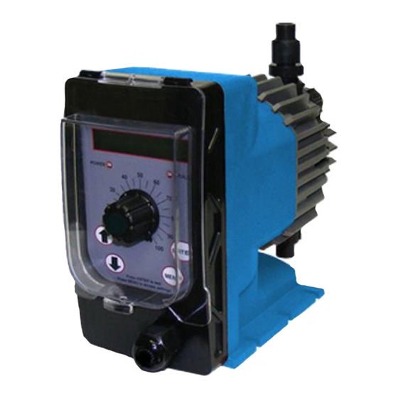
Summary of Contents for DEMA Flex Flow
- Page 1 Manual 0960.F Flex Flow Chemical Metering Pump Installation Maintenance Repair Manual DEMA Eng 10020 Big Bend Blvd. St. Louis, MO 63122 800-325-3362 www.demaeng.com 3/2010...
-
Page 2: Table Of Contents
Manufacturer’s Product Warranty DEMA warrants units of its manufacture to be free of defects in material or workmanship. Liability under this policy extends for 24 months from date of installation. Liability is limited to repair or replacement of any failed equipment or part proven defective in material or workmanship upon manufacturer’s examination. -
Page 3: Introduction
Unpacking The FlexFlow™ pump has been shipped as a complete package, ready for installation. If the shipping carton shows any signs of damage, notify the shipping company immediately upon receipt. DEMA cannot be held responsible for damage from shipping. Unpack the carton and insure the following items are present:... -
Page 4: Installation
Installation A. Location Select a mounting location convenient to the chemical supply as well as a source of power for the pump. Do not install the pump in a location where the ambient temperature exceeds 120 degrees F (50 C). Higher temperatures will affect the output as well as the useful life of the pump. - Page 5 Tubing Connections 3/8" TUBING MUST SLIP OVER NIPPLE 1/4" 1/4" TUBING IMPORTANT ADAPTER THE END OF THE TUBING MUST EXTEND 1/4" BEYOND ADAPTOR Suction Lift vs Flooded Suction Applications Suction Lift Installation Mount the FlexFlow™ pump around the top of the solution tank, not to exceed 5 feet from pump to bottom of tank.
- Page 6 Injection valve installation The injection valve is designed to prevent a back flow and to inject chemical into the line. To work properly, this valve must be mounted within 45 degrees of vertical (see drawing). One end of the injection valve is 1/2” MNPT. Install this end into the piping system.
-
Page 7: Start-Up
Start-Up Priming the pump Plug in pump, set stroke to 100% and strokes per minute to maximum speed. While pump is operating, if fluid begins moving, no further priming is required. If fluid is not moving, open bleed valve approximately one turn until fluid begins to move. When suction line fills, close bleed valve. -
Page 8: Maintenance
When an open condition is seen the pump is not allowed to stroke. Maintenance The DEMA FlexFlow™ pump is designed for long service life with minimum maintenance. If for any reason, maintenance is necessary or desirable, the FlexFlow™ pump is easily maintained. -
Page 9: Liquid End Diagram
C. Liquid End Diagram Item Description Complete Head Kit Injection Valve Foot Valve Suction Valve Discharge Valve Bleed Valve Assembly Pump Head Pump Diaphragm Support Ring Shaft Seal Head Bolts Priming Tube Suction Tubing Discharge Tubing Weight Complete Head Kit includes items: 4,5,6,7,8, and 11... -
Page 10: Pump Replacement Parts
D. Replacement Parts Getting the right materials of construction for your spare parts is easy. Using positions 7-10 of the pump model number, example: B130X1-PFCV. Find the assembly needed and add the codes of your pump’s liquid end after the standard prefix part number for the assembly. Note: For standard pumps using the short model number (example: B130) use the following liquid end codes. -
Page 11: Trouble Shooting Guide
VII. Trouble Shooting PROBLEM CAUSE REMEDY Pump does not achieve Air trapped in suction line Straighten suction line so as to eliminate or maintain prime high spots. Foot valve contaminated or improperly Inspect foot valve screen and assure that installed foot valve is in a vertical position below fluid level. - Page 12 Excessive fluid Failure or lack of antisiphon valve Inspect or add anti-siphon valve. This is caused when system is in a vacuum condition or valve in delivery applications with flooded suction which feeds systems at very low pressures. Excessive stroke rate Lower the stroke rate if adjustable on your pump.
Need help?
Do you have a question about the Flex Flow and is the answer not in the manual?
Questions and answers