
Summary of Contents for Brodie BERT-E
- Page 1 BI-BERT| Revision 01 Model BERT-E Installa on and Opera on Manual Engineered for Accuracy...
-
Page 2: Read Me First
fi tness for a par cular purpose with respect to this manual and, in no event, shall Brodie be liable for any special or consequen al damages including, but not limited to, loss of produc on, loss of profi... -
Page 3: Ordering Information
This product is not recommended for life support applications or applications where malfunctioning could result in personal injury or property loss. Anyone using this product for such applications does so at his/her own risk. Brodie International shall not be held liable for damages resulting from such improper use. -
Page 4: Specifications
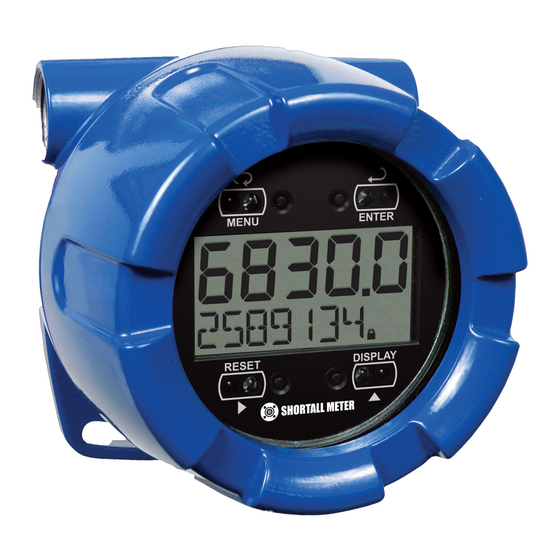
On-Board Data Logging Specifications Except where noted all specifications apply to operation at +25°C. General Five Digits Top Display (0 to 99999) 0.7" (17.8 mm) high, 7-segment, DISPLAY automatic lead zero blanking. Seven Characters 0.4" (10.2 mm) high, 14-segment, automatic lead zero Bottom Display blanking. -
Page 5: Rate Input
Backup power only 10 years Up to 1024 records, recorded 4/day at specific times or at defined time intervals. Record contains DATA LOGGING date, time, rate, total, grand total, and log number. All Models: 500 V opto-isolated input-to-power/OC output with ISOLATION isolated input enabled BPD6830AB2B1:... - Page 6 Field programmable K-Factor converts input pulses to rate in engineering units. May be K-FACTOR programmed from 0.000001 to 9,999,999 pulses/unit. Input 1 signal must be ≥ 1 Hz; input 2 signal may be set anywhere above input 1 setting. CALIBRATION RANGE Minimum input span is 1 Hz.
-
Page 7: Open Collector Outputs
4-20 mA Transmitter Output Rate/process, total, grand total, or disabled OUTPUT SOURCE 4.000 to 20.000 mA for any display range. SCALING RANGE If disabled, the output will output 3.2 mA DISABLE Factory Calibrated: 0.0 to 1000.0 = 4-20 mA output CALIBRATION Output Underrange: 3.8 mA UNDERRANGE... -
Page 8: Product Ratings And Approvals
This information is contained within the serial number with the first four digits representing the year and month in the YYMM format. For European Community: The BERT-E must be installed in accordance with the ATEX directive 94/9/EC, and the product certificate Sira 13ATEX1010X... -
Page 9: Electromagnetic Compatibility
Electromagnetic Compatibility EN 61326:2006 EMISSIONS Safety requirements for measurement, control, and laboratory use – Industrial Group 1 Class A ISM emissions requirements Radiated Class A Emissions EN 61326:2006 IMMUNITY Safety requirements for measurement, control, and laboratory use ±4 kV contact, ±8 kV air 80-1000 MHz @ 10 V/m, RFI –... -
Page 10: Installation
INSTALLATION For Installation in USA: The BERT-E must be installed in accordance with the National Electrical Code (NEC) NFPA 70. For Installation in Canada: The BERT-E must be installed in accordance with the Canadian Electrical Code CSA 22.1. For European Community: The BERT-E must be installed in accordance with the ATEX directive 94/9/EC and the product certificate Sira 10ATEX1116X. -
Page 11: Cover Jam Screw
Mounting The BERT-E has two slotted mounting flanges that may be used for pipe mounting or wall mounting. Alternatively, the unit may be supported by the conduit using the conduit holes provided. Refer to Mounting Dimensions, page 82 for details. - Page 12 Observe all safety regulations. Electrical wiring should be performed in accordance with all agency requirements and applicable national, state, and local codes to prevent damage to the meter and ensure personnel safety. WARNING OC1+ OC1- OC2+ OC2- Figure 1. Connector Board Input Signal Connections Signal connections are made to a barrier terminal mounted in the base of the enclosure.
- Page 13 Flowmeter INPUT LEVEL (Magnetic Pickup Coil) Figure 4. Self-Powered Magnetic Pickup Coil Flowmeter (Coil) +3.0 V SENSOR 100 kOhm Internal Pullup INPUT LEVEL Figure 5. NPN Open Collector Input (NPN) Power Supply SENSOR 100 kOhm Internal Pull-Down INPUT LEVEL Figure 6. PNP Sensor with External Power (PNP) +3.0 V SWITCH CONTACT...
-
Page 14: Dc Power Connection
DC Power Connection Model BPD6830AB2B1 is provided with a terminal labeled P+ and is wired as shown in Figure 9. BPD6830AB2B1 units may be connected to DC power and the battery will function as backup power when DC is lost. The same power supply may be used to power other circuits including a PNP-type sensor, however to maintain input isolation, a separate power supply must be used to power the isolated 4-20 mA transmitter as shown in Figure 10 and/or to power the Opto-Isolated Flowmeter as shown in Figure 3. -
Page 15: Open Collector Output Connections
Open Collector Output Connections Open collector output 1 and 2 connections are made to terminals labeled OC1+ and OC1-, and OC2+ and OC2-. Connect the alarm or pulse input device as shown in Figure 11. Figure 11. Open Collector Output Connections... -
Page 16: Battery Replacement
Battery Replacement The BERT-E includes a battery charge monitor. When the battery is nearing the end of its capacity the screen will periodically flash the message LO BATTERY and the BAT indicator on the screen will flash. The recommended replacement interval for models using the battery as a primary power source is determined by the power and feature use, as shown on page 2. -
Page 17: Setup And Programming
Through-Glass Buttons. Through-Glass Buttons The BERT-E is equipped with four sensors that operate as through-glass buttons so that it can be programmed and operated without removing the cover (and exposing the electronics) in a hazardous area. - Page 18 Through-Glass Button Tips and Troubleshooting The Through-Glass Buttons are designed to filter normal levels of ambient interference and to protect against false triggering, however it is recommended that the Through-Glass Buttons be turned off (slide THRU-GLASS BUTTONS switch to OFF) if there is an infrared interference source in line-of-sight to the display or if the buttons are not needed.
-
Page 19: Buttons And Display
Buttons and Display MENU ENTER RESET DISPLAY Button Description Symbol Status Symbol High Alarm Menu/ Through- Low Alarm Glass Awake MENU Total Alarm RESET Right Arrow/Reset Settings Lockout Password Enabled Through-Glass Power DISPLAY Save/Disable. Up Arrow/ Flashing: Temporarily Disabled Display Due to Mechanical Button Total Display Flashing: Total Overflow... -
Page 20: Enter Button
Press Reset to reset the total, or values displayed in the bottom display (grand total, max, or min). Press Enter after Reset to confirm the reset. Up / Display Button Press Display when in Run mode to display the grand total, again to display the maximum, and again to display the minimum reading since last reset. -
Page 21: Setting Numeric Values
Setting Numeric Values The numeric values are set using the Right and Up arrow buttons. Press Right arrow to select next digit and Up arrow to increment digit. The digit being changed blinks. Press the Enter button, at any time, to accept a setting or Menu button to exit without saving changes. The decimal point is set using the Right or Up arrow button in the Setup, Decimal Point menu. - Page 22 Press Menu, at any time, to return to the previous menu selection. Press and hold the Menu button for 1.5 seconds at any time to return to Run Mode. Changes to the settings are saved to memory only after pressing Enter. ...
- Page 23 Setup Menu Display Functions & Messages The meter displays various functions and messages during setup, programming, and operation. The following table shows the main menu functions and messages in the order they appear in the menu. Display Parameter Action/Setting SETUP Enter Setup menu Setup Input...
- Page 24 Display Parameter Action/Setting Units per minute Minute hour Units per hour Hour Units per day RateU Select rate display units Rate units Set units as gallons Gallons Set units as liters Liters IGAL Set units as imperial gallons Imperial gallons Set units as cubic meters Meters cubed Set units as barrels...
- Page 25 Display Parameter Action/Setting Grtot Set grand total display decimal point Grant total Dsply Set the function of the top and bottom displays Display Set the function of the top display Rate Display rate Rate Total Display total Total BOtnm Set the function of the bottom display Bottom Total Display total...
-
Page 26: Setting Up The Meter (Setup)
Setting Up the Meter (SETUP) The Setup menu is used to select: 1. Input type selection (INPuT) 2. K-factor number and units (FActr) 3. Display rate, total, and grand total units (Units) 4. Rate and total decimal point position (dec.pt) 5. - Page 27 Selecting Input Type (Input) Seven input types may be set. See Rate Input specifications on page 3 for electrical specifications of the inputs. The following input types may be selected: Active (activ) External power supply driven pulse inputs NPN (NPN) Internal pull-up resistor on S+ for NPN inputs PNP (PNP) Internal pull-down resistor on S+ for PNP inputs...
- Page 29 Entering the K-Factor (Factr) The meter may be scaled using the K-factor, or conversion factor, function. Most flowmeter manufacturers provide this information with the device. Enter the K-Factor (Factr) menu and select the units defined with the k-factor (example: pulses/gal), the decimal point with highest resolution possible, and program the K- Factor value.
- Page 30 Important Programming Note: The units selected in this menu are the desired display units only. The units defined by the k-factor of a flow meter are entered in the K-Factor menu as part of the Factor Unit menu programming. See K-Factor Units (FuNiT) on page 27 for details.
- Page 31 The following units may be selected as the base units for rate, total, and grand total. Time base for rate and a multiplier for total and grand total units may also be selected separately. Units Unit Description Set units as gallons Gallons Set units as liters Liters...
-
Page 32: Setting The Time Base (Tbase)
Setting the Time Base (tbase) The meter calculates rate based on rate time base and rate display units. The time base is the unit of time used to calculate the rate, and can be set as units per second, minute, hour, or day. Press the Enter button, at any time, to accept a setting or Menu button to exit without saving changes. - Page 33 Setting the Rate Display Units (rateU) Rate is displayed in terms of a unit of volume, and a time base. The unit selected will be used with the time base to establish the rate unit (example: GAL/S when Units is GAL, and time base is seconds). The custom unit selection (CUST) will require the custom unit to be entered by the user.
- Page 34 Total Units (tot U) This menu is used to select the display units for the total. The base unit and a multiplier prefix are selected. If total and units are selected to display, the multiplier prefix will appear before the total unit (example: MGAL, kL).
- Page 35 Grand Total Units (GtotU) This menu is used to select the display units for the grand total. The base unit and a multiplier prefix are selected. If grand total and units are selected to display, the multiplier prefix will appear before the total unit (example: MGAL, kL).
- Page 36 Automatic Unit Conversions When switching from any standard unit of rate, total, or grand total to any other standard unit, automatic unit conversions are performed by the meter. No unit conversions will be performed when the K-Factor Units (FuNiT) menu is set to custom (CUST). A total or grand total unit conversion will automatically change the displayed total and grand total to the equivalent volume of the newly selected unit.
-
Page 37: Setting The Decimal Point (Dec.pt)
Custom Units Total Conversion Factor (totCF) The total conversion factor is only used when the Units for total have been set to custom (CUST). This menu will not appear if standard display units are selected for total. Total Conversion Factor is used to convert to a custom unit of total display. For example, to display total as quantity of 2.5 gallon containers when the K-Factor units are set to gallons, enter a conversion factor of 2.500. - Page 39 Configuring the Display (Dsply) The top and bottom displays can be independently programmed to display selected information. Top Display (TOp) The top display can be programmed to display rate or total. When displaying total, the top display will only show the 5 least significant digits, with no overflow display, for a total from 0 to 99999. The total rolls over at 99999 to 0 when on the top display.
- Page 40 Bottom Display (bOtm) The bottom display can be programmed to display the following information. 1. Total 8. Alternating grant total, grand total units, and rate units 2. Alternating total and total units 9. Rate 3. Alternating total and custom tag 10.
- Page 41 Custom Tag (TAG) When the bottom display selected includes a custom tag, a User menu will then allow a custom tag to be programmed. Any 7-digit 14-segment label may be entered for a custom tag (examples: RATe, LINE 3, WaTER). Fully alphanumeric values are set using the Right button to select the digit, the Up and Right arrow buttons to select the digit reading, and the Enter button to confirm and select the next digit.
- Page 42 Setting the Toggle Time (TIME) If the bottom display is programmed to toggle (TOGLE), the meter will prompt for a toggle time. In addition, it may require a tag be entered, as shown in the example below. Enter the time in seconds for the unit or tag to display in the bottom window every 10 seconds. The unit may be programmed to display for 1 to 5 seconds.
-
Page 43: Advanced Features Menu
Advanced Features Menu To simplify the setup process, functions not needed for most applications are located in the Advanced features menu. Access the Advanced features menu by pressing Enter at the Advance menu in the Main Menu defined on page 19. The Advanced menu is used to select: 1. -
Page 44: Advanced Features Menu & Display Messages
Advanced Features Menu & Display Messages The following table shows the Advanced features menu functions and messages in the order they appear in the menu. Display Parameter Action/Setting ADVANCE Enter Advanced menu Advanced OUTPUT Setup open collector outputs Out 1 and Out 2 Output OUT 1 Assign function of open collector output 1... - Page 45 Display Parameter Action/Setting OUt 1 Output 1 value Output 1 Dsp 2 Output display 2 value Display 2 OUt 2 Output 2 value Output 2 Save? Save entered analog parameters Save dsabl Turn off the analog output Disable GATE Enter Gate menu Gate Set Low Gate Low gate...
- Page 46 Display Parameter Action/Setting GTrST Select the Grand Total Reset method Grand total reset PASSWRD Enter the Password menu Password Pass Program password to lock meter parameters Password Pass T Program password to prevent total reset Password total Pass GT Enter password to permanently lock out grand total related parameters Password grand total and reset UnLOC...
- Page 47 Display Parameter Action/Setting INTERVL Set interval log time Interval STArT Begin interval logging Start LOGVIEW View data log Log view ALL LOGVIEW View all data log points All log view LOG NUM Go to specific log number Log number ALL ERASE Erase all logs All erase Erase?
- Page 48 Open Collector Outputs (OUTPUT) The meter is equipped with two NPN open collector outputs that may be set up for pulse outputs, alarms, timed pulses, or turned off. Pulse outputs are based on K-factor, total or grand total counts, or one-for-one retransmit for input pulses. Both outputs may be used to generate a quadrature output based on any pulse menu output type.
- Page 49 Output 1 and 2 Setup (OUT 1, OUT 2) The function of open collector output 1 and 2 is configured using the Off, Pulse, Alarm, and Timer menus detailed below. Pulse Output (PUlse) Pulse outputs may be assigned to rate, total, grand total, retransmit, quadrature, or test. Rate Pulse Output (rate) A rate based pulse output is a factor of the rate display and count (output K-factor).
-
Page 50: Alarm Output (Alrm)
Retransmit Output (retr) The retransmitting pulse output will send an output pulse for every input pulse, essentially duplicating the input signal. The output will generate a pulse at the falling edge of every input pulse. No additional programming is required for a retransmitting pulse output. If the maximum output frequency would be exceeded, the meter will display the message pUlse OVERRNG alternating on the display. - Page 52 Rate Alarm (rate) Program the rate set point to trigger the alarm. Rate alarm deadband is determined by the difference between set and reset points. Minimum deadband is one display count. If set and reset points are programmed the same, output will reset one count below set point. Total or Grand Total Alarm (Total, Grtot) Program total or grand total set point.
-
Page 53: Scaling The 4-20 Ma Analog Output (Aout)
Scaling the 4-20 mA Analog Output (Aout) The Analog Output menu is used to program the 4-20 mA output based on display values. The 4-20 mA analog output (if equipped) can be scaled to provide a 4-20 mA signal for any display range selected for either the rate, total, or grand total. - Page 54 Gate Function (GATE) The gate function is used for displaying slow pulse rates. Using the programmable gate, the meter is able to display pulse rates as slow as 1 pulse every 9,999 seconds (0.0001 Hz). The gate function can also be used to obtain a steady display reading with a fluctuating input signal.
- Page 55 Scaling & Calibration (SCALCAL) It is very important to read the following information, before proceeding to program the meter: There is no need to recalibrate the meter for frequency in Hz when first received from the factory. The meter is factory calibrated for Hz prior to shipment. The calibration equipment is certified to NIST standards.
-
Page 56: Scaling The Meter (Scale)
Scaling the Meter (SCale) The pulse input can be scaled to display the process variable in engineering units. A signal source is not needed to scale the meter; simply program the inputs and corresponding display values. A programmed scaled input will work with Automatic Unit Conversions as described on page 34. The units for the display values that must be entered are a combination of the programmed Rate Unit and the time unit (Time UNIT) entered in the Scale menu. - Page 57 Pulse Input Time Unit (Time UNIT) This is the time component for the engineering units of the display values being entered. Enter the appropriate units/second, units/minute, units/hour, or units/day that corresponds to the values being entered at the display 1-32 ( dsp) menus. For example, if the display values are being entered in gallons/second the time unit would be set to seconds.
-
Page 58: Calibrating The Meter (Cal)
Calibrating the Meter (CaL) To scale the meter without a signal source refer to Entering the K-Factor (Factr) on page 27 or Scaling the Meter (SCale) on page 54. The pulse input can be calibrated to display the process in engineering units by applying the appropriate input signal and following the calibration procedure. - Page 59 The meter displays inp 1. Apply a known signal and press Enter. The display will flash while accepting the signal. After the signal is accepted, the meter displays dsp 1 Press Enter. Enter a corresponding display value for the signal input, and press Enter to accept.
-
Page 60: Minimum Input Span
Error Message (Error) An error message indicates that the calibration or scaling process was not successful. After the error message is displayed, the meter reverts to input 2 during calibration or scaling, allowing the appropriate input signal to be applied or programmed. The error message might be caused by any of the following conditions: 1. -
Page 61: Manual Or Automatic Total Reset Function (T Rst)
Total Reset (T Reset) This menu is used to select the ways the total and grand total may be reset. Manual or Automatic Total Reset Function (t rST) For manual reset, select T RESET t rst man and then select whether manual reset will be enabled (Enabl) or disabled (dsabl) using the Up arrow key. - Page 62 Manual or Automatic Grand Total Reset Function (GtrST) For manual reset, select T RESET Gtrst man and then select whether manual reset will be enabled (Enabl) or disabled (dsabl) using the Up arrow key. Press the Enter button to accept. Disabling reset will avoid inadvertent resets of the total via the front reset button.
- Page 63 Setting Up Passwords (PASSWRD) The Password menu is used to program a five-digit password to prevent unauthorized changes to the programmed parameter settings, to restrict the ability to reset the total and grand total, and to permanently lockout the ability to reset the grand total and any grand total related parameters. The lock symbol is displayed to indicate that settings are password protected.
-
Page 64: Disabling Password Protection
Disabling Password Protection To disable the password protection, access the Password menu, select the type of password to be disabled, and enter the correct password as shown below. That password is now disabled until a new password is entered. If the correct five-digit password is entered, the meter displays the message UnlOC (unlocked) and the protection is disabled until a new password is programmed. - Page 65 Non-Resettable Grand Total Locked Menus & Parameters Display Parameter/Menu Action/Setting Locked DECIMAL Factr All K-Factor menu parameters K-factor sCalE All Scale menu parameters Scale All Calibrate menu parameters Calibrate GTrST All the Grand Total Reset menu parameters Grand total reset Pass GT Enter the grand total reset password Password grand total...
- Page 66 Custom (CUSTOM) The Custom menu is used to modify the initial programming menus that appear in the Main Menu when the Menu button is pressed in Run Mode. Changing the default menu setup with the Custom menu feature may change the setup and operation procedures described in this manual.
-
Page 67: System (System)
TOTAL.DP Set to show Total Decimal Point menu Total decimal point GRTOT.DP Set to show Grand Total Decimal Point menu Grand total decimal point SCALE Set to show Scale menu Scale Set to show Calibrate menu Calibrate T BASE Set to show Time Base menu Time base T FACTR Set to show Total Conversion Factor menu... - Page 69 Set Real Time Clock (SETTIME) The real time clock is used to trigger data log events, and is recorded at every logged data point. The menu displays the date and time. Figure 13. Date Display Example The above display example shows the date to be June 27, at 14 hours, 32 minutes, and 36 seconds. The display date will toggle with the year.
- Page 71 There are two ways to configure the time when a data log is recorded. The Log Time feature allows up to 4 data logs to be recorded each day, at specific times. The Log Interval feature allows a data log to be recorded each time a time interval has passed.
-
Page 72: Backup & Restore (Backup)
View Data Log (LOGVIEW) The Log View menu allows on-screen browsing of the data log points stored in the meter. Data points may be navigated by viewing the log number, date and time, total, or grand total amounts. A known log may be jumped to immediately, avoiding a lengthy search for data. -
Page 73: Information (Info)
The save feature (SAvE?) saves all current parameter settings into the memory of the backup restore. The backup restore feature is loaded with factory default settings until a new configuration is saved. The load feature (load?) restores all parameters to the programmed values stored in backup restore memory. - Page 74 Standby Mode (STANDBY) Standby mode is available on battery powered and battery backup models only. The Standby menu is used to enter a power-saving standby mode that will turn off the display and activate a low power mode for the through-glass buttons. Signal processing operations will continue to run.
- Page 75 Operation Front Panel Buttons Operation Symbol Description Hold the Menu Through-Glass button when in power save mode (display will show ) to awaken Through-Glass buttons. Press the Menu button to enter Programming Mode. Press the Menu button during Programming Mode to return to return to the previous menu selections.
- Page 76 The following Through-Glass button information is reprinted from Through-Glass Button Operation on page 15. Through-Glass Button Operation To actuate a button, press and remove one finger to the glass directly over the marked button area. Remove finger to at least 4 inches away from the glass in between button activations.
- Page 77 Through-Glass Button Tips and Troubleshooting The Through-Glass Buttons are designed to filter normal levels of ambient interference and to protect against false triggering, however it is recommended that the Through-Glass Buttons be turned off (slide THRU-GLASS BUTTONS switch to OFF) if there is an infrared interference source in line-of-sight to the display or if the buttons are not needed.
- Page 79 Grand Total Reading (GrTOTAL) The grand total is a separate total that is not reset when the total is reset. This allows the complete total to be tracked by the grand total, while individual batch, or daily totals are reset regularly. To display the grand total, press the Up/Display button.
-
Page 80: Reset Meter To Factory Defaults
Resetting Max/Min Readings (RESET MAXIMUM, MINIMUM) The maximum and minimum readings may be reset by pressing the Reset button while displaying either the maximum or minimum. The display will show RESET to verify the reset of maximum or minimum value. The maximum and minimum must be reset individually. -
Page 81: Factory Defaults & User Settings
Factory Defaults & User Settings The following table shows the factory setting for most of the programmable parameters on the meter. Next to the factory setting, the user may record the new setting for the particular application. Model: ______________ S/N: _______________ Date: _________ Parameter Display Default Setting... - Page 82 Parameter Display Default Setting User Setting Dspl2 Scale/Cal Display 1 1000.0 (N/A) Parameter Lock PASS 00000 (unlocked) Password Total Reset Password PASS T 00000 (unlocked) PASS Grand Total Reset 00000 (unlocked) Password OUT 1 Output 1 OUT 2 Output 2 Low Gate GATE HI GATE...
-
Page 83: Troubleshooting Tips
Troubleshooting The rugged design and the user-friendly interface of the meter should make it unusual for the installer or operator to refer to this section of the manual. If the meter is not working as expected, refer to the recommendations below. Troubleshooting Tips Symptom Check/Action... -
Page 84: Mounting Dimensions
Mounting Dimensions All units: inches [mm] Figure 14. Enclosure Dimensions – Front View... - Page 85 3.35 [85.0] 4.15 [105.5] 4.86 [123.5] 3.22 [81.9] Figure 15. Enclosure Dimensions – Side Cross Section View...
-
Page 86: Quick User Interface Reference
Quick User Interface Reference Pushbutton Function Go to Programming mode, back out one level of programming. Menu Hold to enter Advanced Features mode. Leave grand total/max/min mode. Move to next digit or decimal point position. Go to reset menu Right Arrow Return to last programming menu. -
Page 87: Ec Declaration Of Conformity
EN 60079-31:2008 Tamb -40°C to +75°C EN 61326:2006 IEC 61010-1:2001 & EN61010-1:2001, including Group and National Differences as they apply for AU, CA, and US Community Directives: 94/9/EC ATEX Directive 2004/108/EC EMC Directive Company: Brodie International Co., LLC Date: 06/03/2013... -
Page 88: Warranty Claim Procedures
“Brodie” shall, at its op on, promptly correct any errors that are found by “Brodie” in the fi rmware or Services, or repair or replace F. O. B. point of manufacture that por on of the Goods or fi rmware found by “Brodie” to be defec ve, or refund the purchase price of the defec ve por on of the Goods/Services. - Page 90 This page left blank intentionally.
- Page 91 Notes...
- Page 92 Notes...
- Page 94 The contents of this publica on are presented for informa onal purposes only, and while every eff ort has been made to ensure their accuracy, they are not to be construed as warran es or guarantees, express or implied, regarding the products or services described herein or their use or applicability. Brodie Meter Co., LLC...
Need help?
Do you have a question about the BERT-E and is the answer not in the manual?
Questions and answers