Table of Contents
Advertisement
Quick Links
Advertisement
Table of Contents

Summary of Contents for LAMETAL Stark THM 2500
- Page 1 Original Operating and maintenance manual Back broom (2500, 3000)
-
Page 2: General
General Congratulations on the purchase of your STARK Back broom! For us, the long lifecycle and efficiency of your new equipment is a priority. To keep the broom in top working condition, read this manual carefully before using the equipment. STARK products are engineered and manufactured in Finland, and each of them is equipped according to the needs of the customer. -
Page 3: Table Of Contents
Table of contents General ..............................2 Read before use ........................... 2 DECLARATION OF CONFORMITY ....................4 PURPOSE OF USE .......................... 5 SAFETY PRECAUTIONS ........................5 IDENTIFICATION INFORMATION AND SPAREPARTS ..............6 4.1. Identification plate ..........................6 4.2. Maintenance services ........................6 MAIN PARTS OF THE BACK BROOM ..................... -
Page 4: Declaration Of Conformity
1. DECLARATION OF CONFORMITY The original manufacturer’s EC declaration of conformity: Generic product name: Back broom Models: STARK THM 2500, THM 3000 Manufacturer: Lametal Ltd Kaskenviertäjäntie 2 73100 LAPINLAHTI, Finland tel. +358 17 731 565 Declares that the above-mentioned equipment meets the provisions of Directive 2006/42/EC on machinery and, where applicable, comply with the standards •... -
Page 5: Purpose Of Use
2. PURPOSE OF USE The back brooms are intended for sweeping of streets, yards and areas small and large. 3. SAFETY PRECAUTIONS Make sure you know your equipment before you start using it. Equipment may be operated only by an individual who is thoroughly familiar with its use. Before connecting hydraulics to the base machine, make sure that: there is no-one between the attachment and the base machine the base machine is turned off and the parking brake is on. -
Page 6: Identification Information And Spareparts
4. IDENTIFICATION INFORMATION AND SPAREPARTS 4.1. Identification plate Identification plate is placed on the side of the equipment. The plate includes contact information, machine type, year of manufacture, serial number and weight. (See an example of an identification plate in picture 1 below). The first four numbers in the serial number indicate the month and year of manufacture (month first). -
Page 7: Main Parts Of The Back Broom
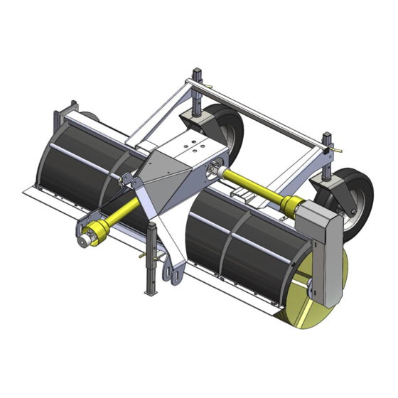
5. MAIN PARTS OF THE BACK BROOM Picture 2. Main parts of the back broom 1) Back broom’s frame 2) Propeller shaft 3) Angle gear box 4) Front propeller shaft 5) Rotating triangle 6) Hydraulic cylinder 7) Broom roller 8) Chain 9) Brush ring 10) Chain’s protective plate Sivu 7 / 20... -
Page 8: Using The Back Broom
6. USING THE BACK BROOM When attaching the back broom for the first time, make sure it is compatible with the base machine by following the instructions below. Always check the compatibility when attaching the back broom to a new base machine. Make sure that the base machine allows the installation of the back broom. -
Page 9: Operating The Back Broom
7. OPERATING THE BACK BROOM Check following before using the back broom: Broom is installed properly to the base machine All locking cotters are in place Hydraulic hoses are attached properly Hoses are intact There are no oil leaks in attachment All functions are in order Learn the functions of the back broom in an enclosed area before actual usage. -
Page 10: Overload Switch
Picture 3. Suitable height for the brush ring 7.2. Overload switch Load on the back broom must be reduced when the overload switch opens. Slow down the driving speed or stop completely until the overload switch operates normally. Overload switch is a safety mechanism which can be damaged when used incorrectly. -
Page 11: Changing The Brush Rings
7.3. Changing the brush rings 1) Detach the protective case. (Picture 5) 2) Loosen the chain and remove it. (Picture 6) 3) Detach broom rollers bolts from the other side. (Picture 7) 4) Detach the bearing’s bolts (2 pc) and socket screws from the bearing. (Picture 8) 5) Remove the end plate located under the bearing by removing the bolts. -
Page 12: Adjusting The Chains
Picture 9. Changing the brush rings 7.4. Adjusting the chains The back broom has a chain at right side, which transfers the power between the propeller shaft and the broom roller’s axle. Check chains for tightness after every 50 operating hours. If chains are too loose, they will be needlessly strained. If chains are too tight, they will strain cogwheels and axle’s bearings. -
Page 13: Removing The Back Broom From The Base Machine
7.5. Removing the back broom from the base machine 1. Lower the back broom down on an even surface on its support legs (picture 12). 2. Adjust the support wheels so that the brush rings don’t touch the ground. 3. Turn off the base machine, apply the parking brake and depressurize the system. 4. -
Page 14: Maintenance Of The Back Broom
8. MAINTENANCE OF THE BACK BROOM 8.1. General safety precautions for the use and maintenance Comply with existing laws and regulations and the instructions given in this manual. Never go under an unsecured device. Always apply the parking brake of the base machine before performing any actions on the device. Only use tools that are in proper working order. -
Page 15: Lubrication Points
8.6. Lubrication points 1. Grease nipples for the broom roller’s bearing (at both ends) 2. Grease nipples for the hydraulic cylinder 3. Grease nipples for the support wheels (at both wheels) 4. Grease nipples for the bearing at the top of the chain 5. -
Page 16: Adding Oil To The Angle Gearbox
8.7. Adding oil to the angle gearbox The angle gearbox in the middle has oil inside. The oil is checked and changed using the dip stick that is located behind the cover box (picture 16). When the device is horizontal the oil level must be at least level with the minimum level shown on the dip stick. -
Page 17: Propeller Shafts
8.8. Propeller shafts The back broom has two propeller shafts (picture 17). Shaft’s grating must be lubricated after every 8 operating hours. Add grease to the grating until it starts to pour out. (Picture 18) Propeller shaft’s shape tubes need to be greased regularly, after every 50 operating hours. Vaseline spray is suitable for greasing (for example Würth HHS2000 or similar). -
Page 18: Hydraulics
9. HYDRAULICS The back broom can be connected in two different ways, either with two (figure 1) or four (figure 2) hoses. When connecting with two hoses, the hydraulics of the basic machine is connected to quick connectors and a separate switch is used to choose whether the broom is rotated or turned. - Page 19 Figure 2. 4-hose hydraulics Sivu 19 / 20...
-
Page 20: Warranty Policy
WARRANTY POLICY 1. Warranty coverage Lametal Oy, the manufacturer of STARK attachments, offers new devices a guarantee which covers material and manufacturing defects in accordance with the terms in this warranty policy. Limitations to the warranty are specified in point 7.
Need help?
Do you have a question about the Stark THM 2500 and is the answer not in the manual?
Questions and answers