Table of Contents
Advertisement
Quick Links
Advertisement
Table of Contents

Related Manuals for Micronix MMC-10 Series


Summary of Contents for Micronix MMC-10 Series
-
Page 2: Table Of Contents
Inventory .......................... 3 Quick Start: Connecting Your Motion Device..............4 Getting Your Target PC Ready ..................5 Quick Start: Using the Micronix Motion Controller Platform ......... 6 Trouble Shooting ........................10 Frequently Asked Questions ....................11 P a g e... -
Page 3: Introduction
Green – Stage has an address and is ready 7. LED Error Indicator 1 a. Red – An error has occurred Features • Integrated controller/driver for MICRONIX USA stick-slip piezo motors • Ultra-compact design • Open loop/closed loop operation •... -
Page 4: Quick Start
2. Quick Start Inventory We will begin the setup process by making sure all the components we will need are accounted for. With every MMC-10 controller, the following should be included: Package Contents: 1. MMC-10 Controller 2. 24V Power Supply 3. -
Page 5: Quick Start: Connecting Your Motion Device
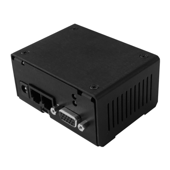
Quick Start: Connecting Your Motion Device. 1. Connect MMC-10 to Motion Devices: Each stage to be used with an MMC-10 will have a male DSUB15 HD connector attached to it. Plug this in to the motor/encoder plug on the MMC-10 unit. This connector will connect the motor to the drive circuitry of the controller, and on closed loop stages will additionally serve to relay the encoder data back to the controller... -
Page 6: Getting Your Target Pc Ready
LED should be lit green. Getting Your Target PC Ready There are a number of ways to control Micronix controllers, but let’s start by setting up the Micronix MCP user interface on your PC. P a g e... -
Page 7: Quick Start: Using The Micronix Motion Controller Platform
If there is uncertainty about which COM port your Micronix device is occupying, or if you are unable to communicate with your Micronix device via com port, skip to the troubleshooting section on page 10 of this manual for help resolving this issue. - Page 8 With a com port identified, it is time to connect to the MMC-10 using the Micronix MCP program installed in section 2.2. Port Control section of Micronix MCP software Port Control a. Select port associated with your MMC-10 device b. Click the Open Port button to connect to the MMC-10 i.
- Page 9 It is important to note here that most Micronix piezo stages do not have limit switches, but use a process that we call “hard stop detection”. The controller tracks the motion of the stage using the encoder and uses positional data to detect hard stops.
- Page 10 Now press the button labeled “Zero” in the position section of the MMCP. Both the calculated and encoder position should now be set at zero. Micronix uses relative encoders, so only changes in position are tracked. Our encoder position is relative to a zero point. A zero point is automatically set every time the controller is power cycled, and can be manually reset at any time.
-
Page 11: Trouble Shooting
Difficulty Installing the Micronix Motion Control Platform To run the Micronix MCP software, you will need the .NET Framework 4.0 or higher to already be installed on the target computer. If the target computer has Windows 7 or later installed and is current on all updates, .NET 4.0 should already be installed. -
Page 12: Frequently Asked Questions
The Micronix MCP programs drop down menu will display the most recently connected com port on the bottom of the list. As such, an easy way to identify a device is to power cycle it, it should now be the last listed com port.
Need help?
Do you have a question about the MMC-10 Series and is the answer not in the manual?
Questions and answers