Table of Contents
Advertisement
Quick Links
Advertisement
Table of Contents
Troubleshooting

Summary of Contents for KENT KVTC-120
- Page 1 1.800.KENT.USA...
-
Page 2: Table Of Contents
2.1.1 Applications 2.1.2 Features KVTC-120 Major components Specification Direction of movement KVTC-120 Machine hazardous locations Installation 3.1 KVTC-120 Foundation plan 3.2 KVTC-120 Layout 3.3 Air pressure and power source 3.4 KVTC-120 Approximate lifting weight 3.5 Level adjustment 3.6 Installation steps... - Page 3 R AD AR 4. Operating Operating panel and MPG Panel function 4.2.1 Mode selector switch 4.2.2 Rapid feed rate switch 4.2.3 Cutting feed rate selector switch 4.2.4 Spindle worktable 4.2.5 Control switch of power tool 4.2.6 Panel function switch 4.2.7 External control function keys 4.2.8 Manual maintenance mode...
- Page 4 R AD AR Tool magazine setting 5.2.1 Adjust zero point of carousel 5.2.2 Adjust tool changing position 5.1.3 Carousel zero point setting 5.5 Pressure adjustment 5.5.1 Hydraulic system settings and adjustment 5.5.2 Air pressure setting and adjusting 5.6 X/Z axis Zero Point Setting 5.6.1 X-axis Zero Point Setting 5.6.2...
-
Page 5: Overall Security
Overall security R AD AR 1. Overall security 1.1 Overall security All members of the factory, such as managers, operators and related personnel, should read this manual carefully before operating. The work piece clamped and cut in high-speed, iron filings may be ejected. It may result in injury. -
Page 6: Machine Safety Requirements
Overall security R AD AR 1.2 Machine safety requirements The machine has several safety features. It can prevent accidental injury to the operator. However, we do not recommend that operator over-rely on those safe model, so we recommend that all operators to remember these safety tips and following safety instructions. -
Page 7: Notice Of Automatic And Manual Mold
Overall security R AD AR 1.3 Notice of automatic and manual mold All operating process is required by regulations of manual. Any person shall not start the machine when the protective covers or security components are removed. Before start the machine, the security doors should be closed. Before cutting the first work-piece, the operator should check the program or the displacement of tool or turret. -
Page 8: Precautions Of Setting And Operating Preparation
Overall security R AD AR 1.4 Precautions of setting and operating preparation The preparation of replacing for parts should be carefully completed. The operator should use the "JOG" mode to check for new operations when start a new processing procedures. The operator should pay attention to all safety conditions when replacing the turret tool. - Page 9 Overall security R AD AR (11) As using the tool compensation function, check the direction and compensation values carefully. The operation with wrong data may result in unpredictable actions. It may damage the work-piece and the machine itself or harm the user. (12) Should check the entered data careful before operating the machine.
-
Page 10: Notice Of Work-Piece Loading
Overall security R AD AR 1.5 Notice of work-piece loading The work-piece loading should be carefully. Be suggested to perform X, Z-axis origin-return action when clamp or remove the work-piece to prevent tool damage caused by collision. When clamp or remove work-piece, make sure the spindle is completely stopped. When clamp the work-piece in the manual mode, the operator should rotate the spindle to check the work-piece has been clamped tightly. -
Page 11: Notice Of Operating Completion
Overall security R AD AR 1.6 Notice of operating completion Should move each axis back to the origin-return position. As spindle stop, all parts should be removed. AS operating is completed, the operator should turn off power completely before leaving the working area. Turn off the power as follows: First press the emergency switch and then off the control panel power switch, then turn off main power in the rear of machine. -
Page 12: Other Notice
Overall security R AD AR 1.8 Other notice The operator should wear appropriate clothing, safety shoes, helmets and goggles. The surrounding around the machine cannot store unnecessary obstacles and the remaining oil, avoid the operator slipping. Do not allow to touch any switches by wet hands. The treatment of waste oil, used oil, cooling water and the iron filings, should be based on local government environmental regulations. -
Page 13: Machine Overall Description
Machine overall description R AD AR 2. Machine overall description 2.1 Applications and Features 2.1.1 Applications KVTC series are computer digital control lathe, designed to provide the metal turning, drilling, threading, tapping and milling. The suitable processing materials are cast iron, cast steel, carbon steel, alloy, stainless steel, brass, bronze and aluminum. -
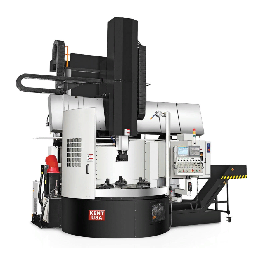
Page 14: Kvtc-120 Major Components
Machine overall description R AD AR 2.2 KVTC-120 Major components Title: Major components KENT INDUSTRIAL USA, Model: Page: R121090901F KVTC-120 1 / 1 INC. - Page 15 Machine overall description R AD AR Assembly Name NO. Parts Number Q'ty Remarks Base Assembly R21210000 Level Adjustment Blocks Assembly R1210100-1 Table Assembly R21210003 Gear Box Assembly R1220000 Column Assembly R1230000 Crossrail Assembly R1240000 Lift Assembly R1241000 Saddle Assembly R1250000 R1251000 R1260000 Live Spindle Assembly...
-
Page 16: Specification
Machine overall description R AD AR 2.3 Specification unit KVTC-120 Mechanical Specifications Table diameter mm (inch) 1,250 (50) Max. swing mm (inch) 1,600 (63) Max. turning diameter mm (inch) 1,400 (55) Max. turning height mm (inch) 1,250 (50) Max. work piece weight... - Page 17 Machine overall description R AD AR unit KVTC-120 RAL Accessories Tool Magazine Capacity tool Tool holder Specifications BT50 Tool size mm (inch) 25 or 32 (1 or 1.25) Max. tool length mm (inch) 400 (15.7) Max. tool weight kg(lb) 50 (110) Max.
-
Page 18: Direction Of Movement
Machine overall description R AD AR 2.4 Direction of movement Table Title: Direction of movement KENT INDUSTRIAL USA, KVTC-120 Model: Page: INC. R121090901F 1 / 1... -
Page 19: Kvtc-120 Machine Hazardous Locations
Machine overall description R AD AR 2.5 KVTC-120 Machine hazardous locations Shaded area in the machine operation may be dangerous, machine operation, personnel and goods do not put their region, to avoid danger. Adjust the maintenance space Dangerous zone Operator... -
Page 20: Installation
Installation R AD AR 3. Installation 3.1 KVTC-120 Foundation plan 1530 1230 1/2" rebar Rebar mesh for top edge 1/2" rebar Table Center Rebar mesh for top edge Rebar mesh for top edge Non shrink grout Insulation material Stone Rebar mesh for bottom edge... -
Page 21: Kvtc-120 Layout
Installation R AD AR 3.2 KVTC-120 Layout Top View Walking Space required for adjusting the electrical box Operator position Work-piece moving route 1900 3600 Front View 5500 Title: Layout KENT INDUSTRIAL USA, KVTC-120 Model: Page: INC. R121090901F 1 / 1... -
Page 22: Air Pressure And Power Source
Installation R AD AR 3.3 Air pressure and power source Air compressor Voltage:220V Transformer Voltage:380V Title: Air pressure and power source KENT INDUSTRIAL USA, KVTC-120 Model: Page: INC. R121090901F 1 / 1... -
Page 23: Kvtc-120 Approximate Lifting Weight
Installation R AD AR 3.4 KVTC-120 Approximate lifting weight Lifting Point Lifting Point 2000kg 8500kg Lifting Point 500kg Stackers 7500kg 500kg Recommend slings Title: Approximate lifting weight KENT INDUSTRIAL USA, KVTC-120 Model: Page: INC. R121090901F 1 / 1... -
Page 24: Level Adjustment
After adjusting column, check the level of table. If not reach to the level status, adjust adjusting level blocks below the table (as ), until the table reaches level status and Z-axis is vertical to the table. Title: Level adjustment KENT INDUSTRIAL USA, KVTC-120 Model: Page: INC. R121090901F... -
Page 25: Installation Steps
Installation R AD AR 3.6 Installation steps Place 9 sets of level adjusting block on 9 points which located on the foundation bolts. Foundation bolt Level adjusting blocks Figure 3.1 Place the base on the 9 sets of level adjusting block by 9 bolt nut of 3 / 4 "×... - Page 26 Installation R AD AR (4) Install the column on the base. Lock with M30 screws (no need to lock) Put the column positioning block into the square groove (about 120×60mm) in the middle of column and base according to the specified direction. Lock adjusting blocks of column by M16 screws on the rear end of base and column (Right and left with one groove for each) and to determine the correct position of adjusting blocks.
- Page 27 Installation R AD AR (9) Lock Z-axis on the X-axis saddle by M20 screws. (10) Connect and fix the snake pipe and oil pipe on the metal sheet of Z-axis. (11) Aim the slot on the top of magazine with tool magazine connected block on the bottom of crossrail then push the magazine to close to tool magazine connected block.
- Page 28 Installation R AD AR (14) Place the coolant tank and chip conveyor below tool magazine. (15) Paper filter frame with M6 screws on the back of the coolant tank. Put the paper filter the paper filter frame. Tool magazine Paper filter Paper filter frame Chip conveyor Coolant tank...
- Page 29 Installation R AD AR (17) Put the gear tank behind the gear box and install the oil return pipe. (18) Put the cooler behind the gear tank. Gear box Oil return pipe Oil return pipe Gear box tank Cooler HBO2RPSA Figure 3.8 (19) Connect the cables according to the mark of cable and electrical box.
-
Page 30: Operating
Operating R AD AR 4. Operating 4.1 Operating panel and MPG Title: Operating panel KENT INDUSTRIAL USA, KVTC-120 Model: Page: INC. R121090901F 1 / 2... - Page 31 Operating R AD AR Emergency stop Tool Fixing / Loosening Tool Fixing / Loosening indication key Title: KENT INDUSTRIAL USA, KVTC-120 Model: Page: INC. R121090901F 2 / 2...
-
Page 32: Panel Function
Operating R AD AR 4.2 Operation and trouble shooting 4.2.1 Mode selector switch HANDLE AUTO RAPID EDIT Figure 4.1 EDIT (1) Edit mode: Switch the selector to edit mode, the CNC controller can be programming and modifying. AUTO Auto mode: Switch the selector to automatic mode and press cycle start button, can start machine and carry out the edited program to perform the processing. -
Page 33: Rapid Feed Rate Switch
Operating R AD AR 4.2.2 Rapid feed rate switch It’s active in RAPID mode. Figure 4.2 Rapid feed-ratio switch: It’s active in fast-moving, zero-return mode or program execute G00 command (Refer to parameter manual ) others are the ratio of fastest moving speed It could turn switch to change the speed under the program running or run in the fast feed-rate mode. -
Page 34: Spindle Worktable
Operating R AD AR 4.2.4 Spindle worktable: It is active in RAPID mode, JOG mode. STOP Figure 4.5 Figure 4.6 ORCM MANUAL MODEL SPINDLE LOAD Figure 4.7 MANUAL MODEL Figure 4.8 Figure 4.9 ( ) When spindle starts under AUTO & MDI mode, choose mode into RAPID, HANDLE, JOG to adjust spindle speed.(Figure 4.5) Before starting worktable, should make sure there are not any person and tools on the table except work-pieces then may perform worktable rotating operation. - Page 35 Operating R AD AR The forward key of spindle worktable: As this function key is "ON", the spindle worktable rotates in positive direction. (5) The stop key of spindle worktable: As this function key is "ON", the spindle STOP worktable stop rotating. (6) The reverse key of spindle worktable: As this function key is "ON", the spindle worktable in reversed rotates direction.
-
Page 36: Control Switch Of Power Tool
Operating R AD AR 4.2.5 Control switch of power tool It is active in RAPID mode, JOG mode. STOP UNCLAMP ORCM Figure 4.10 Figure 4.11 Figure 4.12 The forward key of power tool: As this function key is "ON", the power tool rotates in positive direction. -
Page 37: Panel Function Switch
Operating R AD AR 4.2.6 Panel function switch Figure 4.13 Figure 4.14 Single block key: As this switch is "ON" in auto-run, can execute single block operating, need to press the cycle start(CYCLE START) key to execute the next block. The stop key of power tool: As this function key is "ON", the power tool ratio of MDI program controlled by JOG speed rate. -
Page 38: External Control Function Keys
Operating R AD AR 4.2.7 External control function keys G.H/L LIGHT AIRBLOW WASH.T TOOL COOLANT FORWD BACK Figure 4.15 The gear shifting keys of spindle worktable: It is active in RAPID mode, and G.H/L JOG model. Firstly select “MANUAL MODEL” button As this function key is "ON", the speed of spindle worktable switches to high-speed gear. - Page 39 Operating R AD AR The reversed key of chip conveyor: It is active in RAPID mode, HANDLE BACK mode and JOG mode, s this function key is pressed, the chip conveyor immediately reversed working. As release the hand. Chip conveyor stopped immediately. Before turn chip conveyor on, make sure staff and mechanical safety to avoid damage.
-
Page 40: Manual Maintenance Mode
Operating R AD AR 4.2.8 Manual maintenance mode It’s active in MANUAL MODEL and should work with start button of MANUAL MODEL. (Figure 4.8) MAG DOOR FILTER UNCLAMP MAG CW L- FOR R- FOR MAG CCW L- BACK R- BACK Figure 4.16 The automatic tool magazine switch keys: As this key is "ON", the door of MAG DOOR... - Page 41 Operating R AD AR The reset key of left positioning pin of beam: Used in the maintenance mode, L- FOR let the left side of the positioning pin of beam reset. (Refer to 4.3.2 beams maintenance mode) Please make sure the personnel on safe position away from machine before moving the cross rail, in avoid causing personnel or mechanical damage! The reset key of right positioning pin of beam: Used in the maintenance mode, R- FOR...
-
Page 42: Axial Control Switch
Operating R AD AR 4.2.9 Axial control switch It’s active in RAPID mode, JOG mode Figure 4.17 Z-axis forward control key: As the selector set in RAPID mode or JOG mode, the Z-axis move forward and the speed rate according to the related feeding speed rate.(Refer to: 4.2.2, 4.2.3) Z-axis backward control key: As the selector set in RAPID mode or JOG mode, Filter keys: Press ON, start the paper filter operation;... -
Page 43: Crossrail Position Selector Switch
Operating R AD AR 4.2.10 Crossrail position selector switch START Figure 4.18 Figure 4.19 Figure 4.20 As in HANDLE mode and JOG mode, can carry on crossrail moving. As switch (Figure 4.19) the selector of crossrail position to one point, the Z axis should be zero return and push down the crossrail move button (START)(Figure 4.20)on panel, the crossrail will start to move to selected position. -
Page 44: Power Switch, Data Lock Switch
Operating R AD AR 4.2.12 Power switch, Data lock switch POWER MAIN EDIT PROTECT Figure 4.24 Figure 4.25 Power switch (Figure 4.24): The green button for power "ON", press this key to start the machine, red button for power "OFF". Before shutting the machine, red button for power "OFF". -
Page 45: Emergency Stop Button
This machine has 4 emergency stop buttons. (Figure 4.28) These 4 emergency stop buttons are related. When putting any one of them, the machine will stop. Tool magazine panel Chip cart MPG(refer:4.1 MPG) Operating panel Title: Emergency stop button KENT INDUSTRIAL USA, KVTC-120 Model: Page: INC. R121090901F 1 / 1... -
Page 46: Crossrail Operation And Maintenance
Operating R AD AR 4.3 Crossrail operation and maintenance Be sure to return the Z axis to the origin before moving the crossrail. 4.3.1 Crossrail operation (1) The crossrail operation can only be in HANDLE mode and open the MANUAL MODEL start button. First select the position by selector. -
Page 47: Tool Retraction Function
Operating R AD AR When operating this step, be sure to confirm that the light is on Please Perform operation under the HANDLE mode ( Before moving crossrail, be sure to confirm the safety of personnel and machinery, then perform moving) Press the to up or down the crossrail,when the crossrail manually moved to the desired position (positioning pin higher than... -
Page 48: Prs Using Steps
Operating R AD AR 4.5 PRS Using steps (suitable I.D. processing) Under AUTO mode needs to pause, then restart and return to machining position. When the program is processing to N50 , ( can't use N40 ) Press FEED HOLD and key. -
Page 49: Correction Mode Of Tool Magazine
Operating R AD AR 4.7 Correction mode of tool magazine Tool magazine zero-return correcting steps: Before starting tool magazine correction mode, you must remove the tool from Z-axis first. Figure 4.29 Turn on the Keep relay 3.0 (K3.0 = 1), then the X and Z axes will be interlocked, screen will display the angle of current location of B-axis(It means tool holder as well), the program of "... -
Page 50: Adjustment
Adjustment R AD AR 5. Adjustment 5.1 Crossrail adjustment First, check if X-axis is parallel to work table. If not, check the deviation direction of X-axis, and then adjust. (1) Put the measure tool on Z-axis, and the reading head on the work table. To move X-axis to check deviation direction. - Page 51 Adjustment R AD AR (4) According to deviation direction to choose the adjusted screws. When X-axis deviation direction is left low and right high, fasten the below M12 socket set screw slowly; When X-axis deviation direction is left high and right low,fasten the top M12 socket set screw slowly.
-
Page 52: Z-Axis Adjustment
Adjustment R AD AR 5.2 Z-axis adjustment 5.2.1 Z-axis deviation adjustment (1) Identify Z axis and faceplate centers have been alignment if not record the Z-axis deviation direction. Deviate from right to left Deviate from left to right Table Figure 5.4 (2) Confirm the deviation then release the Z-axis 10×M20 screws. - Page 53 Adjustment R AD AR (3) According the deviation direction to decide release or tight up the screws when Z-axis and faceplate centers alignment then tight up all the screws. When the Z axis deviates from left to right, loosen this site of screws, and then tighten the opposite of screws.
-
Page 54: Z-Axis Deviation Adjustment
Adjustment R AD AR 5.2.2 Z-axis deviation adjustment (1) Confirm Z axis and faceplate center have any deviation if yes, record Z axis deviation direction is forward or backward as Figure 5.7. Column Forward Backward Have deviation Table Figure 5.7 (2) After confirm the deviation direction release the column 12×M30 screws. - Page 55 Adjustment R AD AR (3) Release the upper row 4×M16 screws then according the deviation direction to decide tight up which side of screw set. (Note: When release or tight up the screw they should do it simultaneous to avoid the column deviation.) If the Z axis needs to be moved forward, turn the 2 screws clockwise.
-
Page 56: Magazine Adjustment
Adjustment R AD AR 5.3 Magazine adjustment 5.3.1 Tool carousel positioning adjustment Identify ATC face plate, magazine and tool pocket have been alignment, if not, record the deviation direction and follow the procedures as below to adjust. Center of magazine to tool pocket Figure 5.10 [Adjust carousel to parallel with X-axis. - Page 57 Adjustment R AD AR The beginning setting for K3.0 is 1 now set it as 0. Finish all the setting and re-boots the machine. When No.11#0 as 1, the original point is set already. (10) Set pocket no. 2 as original point. It is different between actual original point pocket no.
-
Page 58: Magazine Positioning Adjustment
Adjustment R AD AR 5.3.2 Magazine positioning adjustment (1) Check magazine and ATC face plate center are identical or not if have any deviation have to know magazine center is off in which direction as Figure 5.11 (backward or forward) Backward Forward Figure 5.11... - Page 59 Adjustment R AD AR (3) Release the upper side of 3×M16 screws then according the deviation direction you may tight up the different screws as Figure 5.13 If the magazine need to move forward then tight up these 2 screws till the magazine to its right position.
-
Page 60: Tool Storage Sensor Adjustment
Adjustment R AD AR 5.3.3 Tool storage sensor adjustment (1) Tooling sensing switch: If tool move to tooling sensing switch cannot find the signal then adjust the tooling sensing switch “ sens” button as Figure above if still cannot sense the signal sens loose the switch 2 screws adjust the switch position back and forth till the sensing switch got the signal. -
Page 61: Tool Magazine Setting
Adjustment R AD AR 5.4 Tool magazine setting Must complete X/Z zero point setting first, then process tool magazine zero point setting. 5.4.1 Adjust zero point of carousel Turn carousel to pocket no. 1. Under EMG statement, adjust the back and forward of carousel, should be parallel to X-axis. - Page 62 Adjustment R AD AR Turn off the power, then turn it on. There is one pocket difference between current position and actual pocket no.1 position. Turn pocket no. 1 to the changing position. Do the zero point setting again, repeat step 3. This setting is pocket no.1 benchmark.
-
Page 63: Adjust Tool Changing Position
Adjustment R AD AR 5.4.2 Adjust tool changing position PMC TYPE: Check if X / Z axis position has been memorized. (P1815) PMM TYPE: Check if X / Z axis position has been memorized. (PAMATER ,NO 0011 # 0) Figure 5.18 Figure 5.19 Check if the verticality of Z-axis is correct. - Page 64 Adjustment R AD AR Enter zero point parameter to set the zero point. (1815 #4 SET 1 / NO0011 #0 SET 1) This position has one difference pocket with actual pocket no.1 position. Turn on the power and turn to pocket no. 1. Then do the zero point setting again.
- Page 65 Adjustment R AD AR (17) Move Z-axis to zero point. (18) Then move X-axis negatively 400mm. This machinery coordinate is X-axis tool changing point. Compare it with parameter P1241 X-axis, then modify error. Figure 5.22 Figure 5.23...
-
Page 66: Carousel Zero Point Setting
Adjustment R AD AR 5.4.3 Carousel zero point setting 0011 # 0 setting 0 NC power off Figure 5.24 NC power on again Message is 224 alarm display Figure 5.25... - Page 67 Adjustment R AD AR In Manual mode, push door and manual key Push MAG C.W. key MG change display number Figure 5.26 Move NO. 1 position Setting 0011 # 0 to 1 (10) Power off, and power on Figure 5.27...
-
Page 68: Pressure Adjustment
Adjustment R AD AR 5.5 Pressure adjustment 5.5.1 Hydraulic system settings and adjustment Placed Hydraulic system unit in the rear of the machine, with3-phase 3HP//5HP drive motor. Fuel tank capacity is 50 liters, hydraulic system requirements for ambient temperature 38 ~ 42°C. Other electrical appliances as follows: L 5.1 3.75... - Page 69 Adjustment R AD AR L5.2 Item Status Item Status 100L Tank Motor Total pressure setting bolts Balance cylinder setting valve Spindle high gear setting bolt Spindle low gear setting bolt Spindle buffer setting bolts Pressure switch 28~32 28~32 Spindle high/low grade Balance cylinder pressure gauge kg/cm²...
- Page 70 Adjustment R AD AR (1) The total pressure adjustment of hydraulic system: a. Refer to Figure 5-12 ,First use a wrench to loosen locking bolt. b. Use a hex wrench into the hexagonal hole, wrench clockwise and watched the total pressure gauge 5-12 .
- Page 71 Adjustment R AD AR The best way to avoid inhalation of air is to connect hydraulic system pipes tightly. Although the piping system is not leakage, it may occur that the air to be inhaled into the oil. The main reason is due to the bad connection for oil pipe.
-
Page 72: Hydraulic System Settings And Adjustment
Adjustment R AD AR 5.5.2 Air pressure setting and adjusting Note: All valves have been set before delivery , to adjust it only as air pressure is too low. The pressure unit fixed on the left of column .Insert the plug of air supply (>... -
Page 73: X/Z Axis Zero Point Setting
Adjustment R AD AR 5.6 X/Z axis Zero Point Setting 5.6.1 X-axis Zero Point Setting Test the center of X-axis. First, adjust the center of Z-axis and the center of back and forward. Based on the center of table, move X-axis left and right to the center. Please see below photo. -
Page 74: Z-Axis Zero Point Setting
Adjustment R AD AR 5.6.2 Z-axis Zero Point Setting Rising Z-axis to the height point (limitation), then there will be a Alarm Press , then move Z-axis downward 5 mm. Set this point as a zero point. Figure 5.32 Set 01815 Z # APC to 1, then reboot. Set 01815 Z # APZ to 1, then reboot. -
Page 75: Maintenance
Maintenance R AD AR 6. Maintenance 6.1 Safety precautions for maintenance To avoid accidents, please follow the instructions below steps to ensure proper operation and safety: Start machine: Check all oil pressure gauges are configured correctly. Check the sliding surface, the amount of lubricants is appropriate or not. If necessary, check the lubricants with bubbles or not. - Page 76 Maintenance R AD AR Precautions while operating the machine: During operation, if there are any unexpected accidents happened, to stop the machine immediately by pressing the emergency stop button. As input tool compensation value, check the the positive and negative sign and decimal point of X-axis and Z axis, to avoid the wrong moves and hit the tool.
-
Page 77: Routine Maintenance Schedule
Maintenance R AD AR 6.2 Routine maintenance schedule 6.2.1 Maintenance cycle time General Notes: Machine should be avoided sunlight, away from heat, in order to maintain accuracy. Machine should be installed in a dry, clean environment with good ventilation, away from the cooling towers, welding machines and cranes etc. Avoid using of unsolicited or low-quality lubricants, only the planned lubricants, or the same level of lubricants can be used. -
Page 78: Repairing And Replacing Parts Precautions
Maintenance R AD AR Lubrication and maintenance: When the oil in fuel tank causes inferior status, such as showing white or odor produced, shall replace the oil immediately. If there is deterioration of hydraulic oil should be replaced immediately. All filters should be kept clean, and the flow of air or hydraulic barriers should be minimal. -
Page 79: Location Of Lubricator
Maintenance R AD AR 6.2.3 Location of Filter This machine has 4 Filter. Should check and clean every half a year. MF-06 CF-06 TK-610 Title: Location of Filter KENT INDUSTRIAL USA, KVTC-120 Model: Page: INC. R121090901F 1 / 1... -
Page 80: Lubrication System
Maintenance R AD AR 6.3 Lubrication system 6.3.1 Standard lubrication table KVTC-120 Vertical Lathe Oil Feeding Reference Lubricating Checking Replacing Parts Capacity Period Period Lubricating oil ISO NO. Table Lubrication Cycle monthly 12 months 150L Chute oil ISO VG 68 &Gear Box... -
Page 81: Standard Lubrication
Maintenance R AD AR 6.3.2 Adjustments of lubricating time This type of lubricator supplies lubricant by PLC control. The supplying is according to the request of operator. How many about the quantity of lubricant should be injected or how long should be injected, it decided by operator. -
Page 82: Machinery Lubrication For Other Parts
Maintenance R AD AR 6.3.3 Machinery lubrication for other parts Coolant tank: This unit installed below the Chip Cart, could be moved away from right side, so that can clean inside parts easily and take away the wasted iron filings. Push the coolant tank back to original position as cleaning finished. -
Page 83: Maintenance And Countermeasures
Maintenance R AD AR 6.3.5 Maintenance and countermeasures Irregular Reason Countermeasures anomaly Periodic cycle time is Periodic cycle time setting error Modify cycle time by the parameters not right (1) Pipe joints leaking. Re-tighten the tubing connector (2) Oil filter blocked Replace or clean filter Increase the oil temperature (heat engine) (3) Oil viscosity is too high... -
Page 84: Coolant System
Maintenance R AD AR 6.4 Coolant system This series of machines covered all around by metal sheet, so when the coolant be operated, it scattered into the working area, but all the coolants will be concentrated in the cooling tank. Coolant flow through the filter, then iron will be separated with the coolants; the coolant in tank can be recycled repeatedly. -
Page 85: Cleaning
Maintenance R AD AR 6.5 Cleaning After installation: Using a special rust inhibitor to protect the machine, so before the operation, use a soft brush or cloth with solvent or kerosene to clean all parts; especially lead screw, rack and all the lighting surface, do not use oil or organic solvents to avoid fire or explosion. - Page 86 Maintenance R AD AR The handling of waste: The handling of lubricating oil, coolant and iron filings must be in accordance with the environmental protection regulation issued by local government. Iron filings must be removed and collected in an appropriate and well-ventilated place. Do not left the iron filings in the machine inside after working.
-
Page 87: Troubleshooting
Troubleshooting R AD AR 7. Troubleshooting 7.1 Troubleshooting for spindle table Spindle table unable to turn: The related programs appeared warning signals check the program for errors according to the normal steps to correct the errors. Spindle table motor overheating: Confirm the motor loading, change the program or reduce the spindle speed. -
Page 88: Troubleshooting For Others
Troubleshooting R AD AR 7.3 Troubleshooting for others The sliding surface of X / Z axis cannot be lubricated: To check the quantity of lubricant, if the oil is not reduced, the pump must have a problem. Should check or replace the pump. Pipes or valves may be blocked;... -
Page 89: Troubleshooting For Hydraulic Circuits
Troubleshooting R AD AR 7.4 Troubleshooting for hydraulic circuits Solenoid valve troubleshooting Solenoid valve Failure Countermeasure Reason Remove and clean-up solenoid valve. Solenoid valve inside having If cannot successfully removed from the valve body, foreign or impurities. the body may have adhesion on it. Completely remove the adhesion. - Page 90 Troubleshooting R AD AR Electromagnetic coil burn out (DC24V) Countermeasure Reason Check the voltage is abnormal or not, Voltage overload or insufficient. reset the voltage in range from 90 to 110%. Maintain the oil temperature at 70°C, the ambient Ambient temperature is too high. temperature of rectifier at 50°C or less.
- Page 91 Troubleshooting R AD AR Pump motor troubleshooting Electromagnetic coil burn out (DC24V) Countermeasure Reason Hydraulic oil with air. Check the connecting status of pipes and the fuel level. Because the oil leakage from the Using with function of pressure compensation, can manifold valve, resulting pass stable pressure and constant flow of lubrication.
- Page 92 Troubleshooting R AD AR Pump damage or wear Countermeasure Reason Inappropriate hydraulic oil. Replacing the appropriate hydraulic oil. Remove foreign, check the filter is blocked or not and Hydraulic oil contaminated. clean it, replaced with new hydraulic oil. Check valves and accumulators. Check the diameter of two connected pipe, Abnormal pressure.
- Page 93 Troubleshooting R AD AR Valve action abnormal Countermeasure Reason Due to the foreign winding or rust Remove and clean. make the valve action affected. If failure, replace it. Pipe too narrow leading to Replace larger pipe or valve. heat generated. Improper operation or the Check, replace it if necessary.
-
Page 94: Troubleshooting For Special Conditions
Troubleshooting R AD AR 7.5 Troubleshooting for special conditions Tool vibrating while cutting: The work piece without proper fixed, re-confirm the clamping conditions of jaws. Using the improper size of tools, tools shall be suitable for processing environment and processing material. The tip does not work with the centerline of spindle table, adjust the tip and make it in the center line with spindle table. -
Page 95: Alarm List
Troubleshooting R AD AR 7.6 Alarm list ALARM When any ALARM display, will light up. EXPLANATION LOCATION DESCRIPTION ALARM NUMBER TROUBLE SHOOTING A0.0 HYD.PRESSURE AL AL 1000 Check pressure switch and circuit. X8.5 A0.1 HYD.OIL LEVEL LOW AL 1001 Check hydraulic oil, level switch and circuit. X8.6 A0.2 TABLE FILTER AL AL 1002... - Page 96 Troubleshooting R AD AR EXPLANATION A1.4 GEAR NOT IN POSITION AL 1012 Check photoelectric switch and circuit. X8.0/X8.1 A1.5 GEAR POSITION ERROR AL 1013 Check photoelectric switch and circuit. X8.0/X8.1 A1.6 SPINDLE M3/M4,ROTATING SPEED MUST STOP AL 1014 Spindle exchange H/L gear must stop(M5) A1.7 SPINDLE RUNING CAN'T USE UNCLAMP(M68/M69) AL 1015...
- Page 97 Troubleshooting R AD AR EXPLANATION A3.1 Z AXIS MUST FIRST ZRN AL 1025 Z axis must be back to zero position. A3.2 STEPWISE MOTOR OVERLOAD AL 1026 Check motor, overload switch and circuit. X3.5 A3.3 MAGAZINE HAVE TOOLS AL 1027 Check if there are duplicate tooling in the magazine pocket.
- Page 98 Troubleshooting R AD AR EXPLANATION EXPLANATION A4.6 SPINDLE1(2) SPEED MUST STOP AL 1038 Spindle must be stop then it can be run. A4.7 TOOL TYPE ERROR(MUST MILLING TOOL) AL 1039 tool mode error. A5.0 Cs ON,CAN'T USE SPINDLE H/L GEAR CHANGE AL 1040 Cs mode, spindle1 cannot switch between high and low gears A5.1...
- Page 99 Troubleshooting R AD AR EXPLANATION EXPLANATION A6.3 SPINDLE2 BRAKE PIN ERROR AL 1051 Check sensor and circuit. (X4.5/X6.0_Y5.5 / Y5.7) A6.4 Zf BOX OIL PRESSURE LOW AL 1052 Check pressure switch and circuit. X4.5 A6.5 SPINDLE2 RUNNING AL(M3) AL 1053 Check the electrical manual A6.6 SPINDLE2 RUNNING AL(M4)
- Page 100 Troubleshooting R AD AR EXPLANATION A21.0 -X AXIS OVER TRAVEL AL 2008 Press "O.T." then moving axis. A21.1 +X AXIS OVER TRAVEL AL 2009 Press "O.T." then moving axis. A21.2 +Z AXIS OVER TRAVEL AL 2010 Press "O.T." then moving axis. A21.3 -Z AXIS OVER TRAVEL AL 2011...
- Page 101 Troubleshooting R AD AR Service information All rights reserved KENT INDUSTRIAL USA, INC. copyright 2020-2022...
Need help?
Do you have a question about the KVTC-120 and is the answer not in the manual?
Questions and answers