Table of Contents
Advertisement
Quick Links
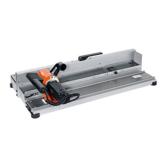
M35.7200.NA – Bottom router
Safety, set-up, operating and maintenance
instructions
NA - EN
Ensure that the instr uc tions have b een
fully read an d un d er stoo d b efore o p eratin g
the b ot tom router. O n l y a p p r o p r iate l y
t r a in e d a n d a u t h o r ize d p e r s o n n e l may
o p e r ate t h e b ot to m r o u te r.
Advertisement
Table of Contents

Subscribe to Our Youtube Channel
Related Manuals for BLUM M35.7200.NA

Summary of Contents for BLUM M35.7200.NA
- Page 1 M35.7200.NA – Bottom router Safety, set-up, operating and maintenance instructions NA - EN Ensure that the instr uc tions have b een fully read an d un d er stoo d b efore o p eratin g the b ot tom router. O n l y a p p r o p r iate l y t r a in e d a n d a u t h o r ize d p e r s o n n e l may o p e r ate t h e b ot to m r o u te r.
-
Page 2: Table Of Contents
M35.7200.NA – Bottom router Table of contents A – Safety Intended use Warning signs Position of warning signs B – Reference diagrams C – Installation and start-up Attaching to the work area Connecting the dust extraction system Connecting the power supply D –... -
Page 3: Intended Use
WARNING Intended use: The bottom router is only intended to process drawer bottoms for the Blum LEGRABOX and TANDEMBOX. The bottom router may only be used under the following conditions: ■The bottom router may only be operated by fully trained personnel. - Page 4 ➢ Do not make any changes or alterations to the bottom router. ➢ For your own safety, use only those accessories which are recommended or specified in the instruction manual or Blum sales catalog. ➢ Check the electrical cable for damage.
-
Page 5: Warning Signs
➢ The bottom router is only intended for use by one person. ➢ Ensure that the average air velocity for dust extraction system is at least 20 m/sec. ➢ The negative pressure in the dust extraction system must be 250–300 mbar. ➢... -
Page 6: Position Of Warning Signs
Ser.No.: MB 00017 machine from electrical before operation. 1X230 V 50/60 Hz 1,05 kW power before cleaning or 29 kg / servicing 64 lbs 16000 1/min Boden - Falzgeraet Ref.No.: M35.7200.NA Julius Blum GmbH - A - 6973 Industriestrasse 1 BA-166... -
Page 7: B - Reference Diagrams
B – Reference diagrams Depending on device type not part of the scope of delivery. Part number: M35.ZD19 Fixing board (delivered loose) Support stop Stop bar Shaft holder Cutter DM 44 Runner Work top Support Depth stop Wood stop Clamping lever Dust extraction socket Clamping plate Transportation lock... - Page 8 M35.7200.NA – Bottom router Reference diagram for Router carriage Rocker switch Flange surface Sliding film Notch cutter Spacer sleeve Cutter DM 44 Allen wrench SW3 TORX T20 TORX T9 TORX T15 BA-166...
- Page 9 Operating elements Clamping lever Press down the clamping lever [8] to secure the work piece. Rocker switch The rocker switch [20] is used to switch the bottom router off and on. Non-stop operation is not possible. In the event of overheating due to overload, the motor will be switched off by the temperature monitoring.
-
Page 10: Installation And Start-Up
M35.7200.NA – Bottom router C – Installation and start-up Dimensions and weight Height (H): ___________________________________________________ 250 mm (9 7/8") Width (W): __________________________________________________ 580 mm (22 7/8") Depth (D): ______________________________________________________ 990 mm (39") Weight: _________________________________________________________ 29 kg (64lb) ➢ Only use in dry, enclosed rooms. - Page 11 WARNING The bottom router must be securely connected to the workbench. Failure to heed this warning may result in personal injury and material damage. The following fixing methods are intended for the bottom router: - fixed attachment to the work top - removable attachment to the worktop Fixed attachment to worktop min.
- Page 12 M35.7200.NA – Bottom router ➢ Position the fixing board [1] within the table length and screw to the frame. min. Ø 5 mm min. Ø 13/64“ ➢ Secure the bottom router to the work top with fixing boards [1] and screw clamps.
-
Page 13: Connecting The Dust Extraction System
Connecting the dust extraction system ➢ Insert an extraction hose with an inner diameter of 50 mm (2") into the dust extraction socket [9] and secure it. Dust extraction socket [9] outer diameter 50 mm (2"). ➢ Ensure that the average air velocity for the dust extraction system is at least 20 m/sec. -
Page 14: Information About Routing
M35.7200.NA – Bottom router equipment-grounding conductor. lf repair or replacement of the electric cord or plug is necessary, do not connect the equipment-grounding conductor to a live terminal. Check with a quahfied electrician or service personnel if the grounding instructions are not completely understood, or if in doubt as to whether the tool is properly grounded. -
Page 15: Routing With Wood Stop
Routing with wood stop [7] for coated work pieces The wood stop [7] prevents torn edges and edge bands. When processing backs, the use of the wood stop [7] is strongly recommended. The wood stop [7] is designed for small processing quantities and must therefore frequently be replaced. - Page 16 M35.7200.NA – Bottom router Replacing the wood stop [7] The wood stop [7] becomes worn through frequent routing. This can lead to torn edges on the work piece. To avoid this, the wood stop [7] must be reworked, if necessary.
- Page 17 ➢ Reposition the wood stop [7] using the next through-hole. ➢ The wood stop [7] can be reworked twice.
-
Page 18: Processable Products, Required Accessories, Work Steps
M35.7200.NA – Bottom router E – Processable products, required accessories, work steps Panel thickness 15 - 16 mm (9/16" - 5/8") Selecting Set-up Notch Cutter fittings Drawer bottom [30] 38 (1 1/2“) In scope of delivery NOTE ■ The cutter M35.ZF44.03 should not be used in the processing of panel thicknesses up to 16 mm (5/8"). - Page 19 Set-up Processing Depth stop [6] Wood stop [7] Support [5] Clamp work piece Route work piece M35.0035.01 M35.ZT01...
-
Page 20: Panel Thickness 17, 18, 19 Mm / (11/16" To 3/4")
M35.7200.NA – Bottom router Panel thickness >16 - 19 mm (5/8“ - 3/4“) For restrictions for Blum products with panel thickness greater than 16 (5/8") and up to 19 mm (3/4") – see page 46: Selecting Set-up Back [31] Notch... - Page 21 Set-up Processing Support stop [12] Depth stop [6] Wood stop [7] Support [5] Clamp work piece M35.ZD19 M35.0035.01 M35.ZT01 Route work piece M35.0035.01 M35.ZT01 Set-up Processing Support stop [12] Depth stop [6] Wood stop [7] Support [5] Clamp work piece M35.ZD19 M35.0035.01 M35.ZT01...
-
Page 22: Stop Bar
M35.7200.NA – Bottom router F – Set-up WARNING Serious cuts. Failure to heed this warning may result in personal injury. ➢ The bottom router must be disconnected from the power supply. Stop bar [13] (optional accessory Part number: M35.ZD19) ➢ Remove the stop bar [13] from the parked position. -
Page 23: Support Stop
Support stop [12] (optional accessory part number: M35.ZD19) ➢ Remove the support stop [12] from the parked position. ➢ Mount the support stop [12] in the working position. ➢ Mount the depth stop [6] or wood stop [7] in the furthest forward position. See page 25. - Page 24 M35.7200.NA – Bottom router The support stop [12] must be aligned. ➢ Check whether a right angle is present. If there is no right angle, proceed as follows: ➢ Loosen the screw of the support stop [12]. ➢ Rotate the support stop [12] until a right angle is formed.
-
Page 25: Depth Stop
Positioning the depth stop [6] ➢ Mount the depth stop [6] in accordance with the drawer nominal length. ➢ When processing the back [31], the depth stop [6] must always be mounted in the furthest forward position. Positioning the wood stop [7] ➢... -
Page 26: Clamping The Work Piece
M35.7200.NA – Bottom router NOTE G – Clamping the work piece ■ There should be no wood chips on the work top [4] and stop surface as they can affect the accuracy of the notch or damage the surface of the work piece. -
Page 27: Clamping The Back
CAUTION ■ Keep your hands away from the clamp (K). ➢ Keep the drawer bottom [30] pressed down on stops [6] [7]. ➢ Push down the clamping lever [8]. ➢ Check again that the work piece is lying flat against the stops. NOTE Clamping the back [31] ■... - Page 28 M35.7200.NA – Bottom router ➢ Push the back [31] onto the stop bar [13], support stop [12] and stops [6] [7], as shown. CAUTION ■ Keep your hands away from the clamp. ➢ Keep the work piece [31] pressed against the stops.
-
Page 29: Routing The Work Piece
H – Routing the work piece ➢ Switch on the dust extraction system. NOTE Routing the drawer bottom ■ The dust extraction system must always be switched on in order to remove wood chips and dust. WARNING Cutting tools can cause serious injury. ➢... - Page 30 M35.7200.NA – Bottom router ➢ Push the carriage [S] gently into the drawer bottom [30]. ➢ At the end of the drawer bottom [30], gently draw the carriage out from the material. NOTE ■ Never turn off the motor during the routing and return process. This could damage the motor or the notch cutter [23].
-
Page 31: Routing The Back
Routing the back [31] ➢ Switch on the dust extraction system. NOTE ■ The dust extraction system must always be switched on in order to remove wood chips and dust when routing. WARNING Cutting tools can cause serious injury. ➢ No more than one operator may use the bottom router at a time. - Page 32 M35.7200.NA – Bottom router ➢ Push the carriage [S1] gently into the back [31]. ➢ At the end of the back [31], gently draw the carriage out from the material. NOTE ■ Never turn off the motor during the routing and return process. This could damage the motor or the notch cutter [23].
-
Page 33: Maintenance
I – Maintenance WARNING Serious cuts. Everyday cleaning Failure to heed this warning may result in personal injury. ➢ The bottom router must be disconnected from the power supply before cleaning and maintenance. CAUTION ■ Wear eye protection during cleaning work. NOTE ■... - Page 34 M35.7200.NA – Bottom router Removing the motor If the motor needs to be removed for maintenance, cleaning or replacement purposes, proceed as follows: WARNING Serious cuts. Failure to heed this warning may result in personal injury. ➢ The bottom router must be disconnected from the power supply before cleaning and maintenance.
- Page 35 ➢ Place the motor [40] in the shaft holder [2]. Installing the motor ➢ All the fixing and clamping surfaces [21] on the carriage [S1] and motor [40] must be free of dust and wood chips. ➢ Push the motor carefully on to the flange surface [21]. Damage to the cutting inserts is possible.
-
Page 36: Removing And Installing The Motor
M35.7200.NA – Bottom router Cleaning the housing If the housing [G] of the carriage [S1] is filled with wood chips or if the cutter is blocked, proceed as follows: Removing and installing the motor ➢ Remove the wood chips from the housing [G]. - Page 37 Retrofitting cutter DM 44 [14] Removing and installing the motor (optional accessory Part number: M35.ZD19) ➢ Turn the nut [42] clockwise using the IM spanner. ➢ Remove the spacer sleeve [24]. ➢ Mount the cutter DM 44 [14].
-
Page 38: Changing The Cutting Inserts
M35.7200.NA – Bottom router Changing the cutting inserts Changing the cutting inserts Removing and installing the motor WARNING Serious cuts. Failure to heed this warning may result in personal injury. ➢ The bottom router must be disconnected from the power supply before cleaning and maintenance. - Page 39 ➢ Clean the pre-cutter [50] using a dry cloth. ➢ Turn the pre-cutter [50] 90 degrees. ➢ Tighten the screw in the pre-cutter [50] by turning it clockwise. NOTE ■ Only the TORX® key provided may be used.
- Page 40 M35.7200.NA – Bottom router hex key SW3 ➢ Loosen the screw for the cutting insert [51] by turning it counter clockwise. ➢ Clean the base of the cutting inserts [51] using a dry cloth. ➢ Turn the cutting insert [51] 180 degrees.
- Page 41 ➢ Position the cutting insert [51] using the setting gauge [52]. hex key SW3 ➢ Tighten the screw for the cutting insert [51] by turning it clockwise. NOTE ■ After all four pre-cutter positions have become worn, the entire set consisting of pre-cutters [50] and cutting inserts [51] must be replaced.
- Page 42 M35.7200.NA – Bottom router J – Troubleshooting Fault Possible cause Remedy Incorrect notch dimensions Work piece not clamped correctly ➢ See page 26 Dirty stops ➢ See page 33 Dirty work top ➢ See page 33 Work piece is not flat against the sup- ➢...
-
Page 43: K - Spare Parts
K - Spare parts When ordering spare parts, state the year of construction and serial number. M35.ZF44.03 M35.ZF60.03 M35.ZW40 M35.ZW14W M35.ZW40W... -
Page 44: L - Bottom Router Set
M35.7200.NA – Bottom router L – Bottom router set Bottom router M35.7200.NA Cutter M35.ZF0-60.03 FRAE-KO Dust extraction socket M51N0603 TRI+ZUT Spanner 19 Allen key 6 Disposal ➢ Dispose of all mechanical components of the bottom router in accordance with local regulations. -
Page 45: Technical Data
Panel thickness: _______________________________________ 15–19 mm (9/16" - 3/4") Serial tag 2015 Ser.No.: MB 00017 1X230 V 50/60 Hz 1,05 kW 29 kg / 64 lbs 16000 1/min Boden - Falzgeraet Ref.No.: M35.7200.NA Julius Blum GmbH - A - 6973 Industriestrasse 1 Device type: Bottom router... - Page 46 16 mm (5/8") –19 mm (3/4") For TANDEMBOX and LEGRABOX, Blum recommends using a panel thickness of 16 mm for back and bottom. The following limitations are to be taken into account when using thicker panel material (up to 19 mm).
- Page 47 Notes...
- Page 48 Blum partners worldwide can be found at: www.blum.com/addresses Blum Inc. 7733 Old Plank Rd. Stanley NC 28164 Tel.: +1 800-438-6788 Tel.: +1 704-827-1345 Fax: +1 704-827-0799 www.blum.com Blum Canada Limited 7135 Pacific Circle MISSISSAUGA ON L5T 2A8 CANADA Tel.: +1 905 670 7920 Tel.: +1 800 670 9254...
Need help?
Do you have a question about the M35.7200.NA and is the answer not in the manual?
Questions and answers