
Related Manuals for Adicos M-BUSMASTER XF

Summary of Contents for Adicos M-BUSMASTER XF
- Page 1 Operating Manual M-BUSMASTER GTE Industrieelektronik GmbH | Helmholtzstr. 21, 38 – 40 41747 Viersen | Germany | +49 2162 3703-0 | info@gte.de...
- Page 2 ADICOS M-BUSMASTER XF Operating Manual Article number: 420-2410-003 Index: EN20 Release date: 12.02.2020 – Translation – Manufacturer: GTE Industrieelektronik GmbH Helmholtzstr. 21, 38-40 41747 Viersen GERMANY Support hotline: +49 2162 3703-0 E-Mail: support.adicos@gte.de © 2020 GTE Industrieelektronik GmbH – This document and all figures contained may not be copied,...
- Page 3 It controls communica- tion with up to 255 ADICOS detectors via the ADICOS M-Bus and serves as the interface be- tween the ADICOS special fire detector and a service PC based standardly on RS-232; can also be based on Ethernet with an expansion module.
-
Page 4: Table Of Contents
Cleaning............20 Replacing ADICOS M-BUSMASTER XF....... 20... - Page 5 Disposal............. . 23 420-2410-003 EN20 ADICOS M-BUSMASTER XF...
-
Page 6: About This Manual
Objective This manual describes how to properly install, wire, start up and operate the ADICOS M-BUSMASTER XF. Once the device has been successfully started up, this document serves as a reference in the event of malfunctions. It is intended to be used only by properly qualified personnel. (–› Chap. 2, For your safety) Explanation of Symbols This manual follows a certain structure to make it easy to work with and understand. -
Page 7: Abbreviations
ADICOS control panel BMZ-30 ADICOS M-BUSMASTER M-BM ADICOS NT V40-A3 - power supply for special fire detector Storing this Manual Store this manual near the fire detectors, in a place where it can easily be accessed when needed for reference. -
Page 8: For Your Safety
Intended use also includes following the instructions in this manual and complying with all relevant local regulations. The ADICOS M-BUSMASTER XF may not be used for any other purpose. If the device is used in any other way, or if changes are made to the product, including in the course of installation and maintenance, the warranty claim is no longer valid. -
Page 9: Qualification Required Of Personnel
• Only properly trained personnel may perform installation work. Only properly trained and qualified persons may work on ADICOS equipment. Qualified per- sons are those who have received relevant professional training, have the required skills and experience and who are aware of applicable regulations, enabling them to work on electrical equipment and detect potential hazards. -
Page 10: Description Of Product
The M-BUSMASTER XF power supply is 230 VAC. The device also has an input for an uninterrupt- ible power supply with 24 VDC. When systems are spread out over a large area, the M-BUSMAS- TER XF can also be used as a repeater. -
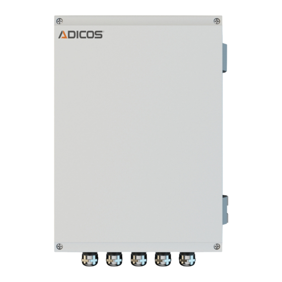
Page 11: Overview
Overview Fig. 1 Description Grounding Supply voltage Connecting terminal ADICOS M-Bus Connecting terminal service PC (pre-configured cables) Cable duct Slot for Ethernet card (optional) Scope of Delivery Check that the delivery is complete and no items are damaged. The scope of delivery includes: M-Busmaster –... -
Page 12: Terminal Assignment And Connections
; check proper polarity (Refer to circuit board label) Current consumption: max. 4 A X2 – M-Bus output on ADICOS M-BUSMASTER XF Connection for two-wire bus system, for communication with the detectors. It is also possible to supply current to the detectors via this bus. - Page 13 X5 – optional M-Bus input When the PC and the ADICOS M-BUSMASTER XF are too far apart, they cannot communicate via the serial interface. This is why the ADICOS M-BUSMASTER XF can be connected to the PC via the optional network card.
-
Page 14: Internal Led Indicators
Fuse Yellow Output fuse has triggered. Overload Overload: The current consumption is greater than 1.5 A. To remedy this issue, remove consumers from the bus or use an M-Bus repeater. Normal Green Device is ready. 420-2410-003 EN20 ADICOS M-BUSMASTER XF... -
Page 15: Jumper
RS-232 interface to a PC with ADICOS software. M-BUS Repeater If the setting “Operation via M-Bus input” was selected, the ADICOS M-BUSMASTER XF works in slave mode. This means that the data is not transmitted to a PC but to a higher-ranking M-Bus master instead. -
Page 16: Fuses
DESCRIPTION OF PRODuCT Fuses Fig. 6 Mains fuse 230 V 1 A, slow-blow Mains fuse 24 V 4 A, slow-blow Output fuse M-Bus 2.5 A, slow-blow 420-2410-003 EN20 ADICOS M-BUSMASTER XF... -
Page 17: Functioning
The M-Busmaster facilitates communication between the master computer and the devices in the ADICOS series, and it serves as a level converter for the signals from the M-Bus to RS-232. An additional ADICOS M-BUSMASTER XF can act as a repeater to expand large systems. This allows the network to be extended and the number of devices connected to be increased. -
Page 18: Wiring Specifications
DESCRIPTION OF PRODuCT Vibration The electronics contained in the ADICOS M-BUSMASTER XF can be damaged when subjected to vibration. If there are any sources of strong vibration near where the device is installed, it has to be positioned such that it is immune to the vibration. -
Page 19: Mounting
5.3.3 Optional LAN Connection with Ethernet Card The ADICOS M-BUSMASTER XF can be ordered with an Ethernet card if needed. The addition- al board is in the slot and the internal connecting cables are attached before the device leaves the factory. The LAN cable still has to be connected. -
Page 20: Commissioning
When using ADICOS detectors, measure the voltage at terminals on the connector assemblies or the respective contacts on the connection cables. Integrating M-BUSMASTER XF into a Network First connect a service PC to the ADICOS central unit and install the central software on the service PC. 6.3.1... - Page 21 COMMISSIONING Fig. 8 Add one or more ADICOS detectors to the query, e.g. using the autoscan feature. While the service PC is communicating with the detectors connected in the field, the red LED (reply) as well as the yellow LED (query) should be flashing.
- Page 22 Changing IP Address Select the device to be changed from the list. Then click “Assign IP.” The wizard used to adapt the IP address opens. Fig. 11 Select “Assign a specific IP address“ and click “Next.” 420-2410-003 EN20 ADICOS M-BUSMASTER XF...
- Page 23 COMMISSIONING Fig. 12 Enter the desired IP address and the subnet mask, then click “Next.” Fig. 13 Click “Assign.” The new IP address is programmed. Fig. 14 420-2410-003 EN20 ADICOS M-BUSMASTER XF...
- Page 24 Port: 10001 Click “OK” to confirm the settings. Add ADICOS detectors to the query, e.g. using the autoscan feature. While the service PC is communicating with the connected detectors, the red LED (reply) as well as the yellow LED (query) should be flashing.
-
Page 25: Checking Bus Communication
OPERATION Checking Bus Communication Once all of the devices have been started up and the central (host) computer and ADICOS M-BUSMASTER XF have been switched on, the ADICOS central software can be opened. The software enables each separate device to be integrated and checked using the central computer. -
Page 26: Failure
... single detectors are not Line interrupted Measure the volt- – – communicating Power supply to de- age in the terminal – tector(s) is disrupted block connector Check that voltage is – being supplied and there is M-Bus voltage 420-2410-003 EN20 ADICOS M-BUSMASTER XF... -
Page 27: 10 Technical Data
-10 … 60 °C Relative humidity: < 95 % relative humidity (non-condensing) Enclosure: Coated die-cast aluminum (corrosion-resis- tant) Dimensions (H x W x D): 72,5 x 208 x 303 mm Weight: 3,27 kg Degree of protection: IP 65 420-2410-003 EN20 ADICOS M-BUSMASTER XF... -
Page 28: 10.1 Dimensions
Fig. 8 Disposal Return the device to the manufacturer when it reaches the end of its serviceable life. The manufacturer will ensure that the components are disposed of properly, in an environ- mentally friendly manner. 420-2410-003 EN20 ADICOS M-BUSMASTER XF... - Page 29 DISPOSAL 420-2410-003 EN20 ADICOS M-BUSMASTER XF...
Need help?
Do you have a question about the M-BUSMASTER XF and is the answer not in the manual?
Questions and answers