Table of Contents
Advertisement
Quick Links
Advertisement
Table of Contents

Summary of Contents for AMIC OOT550-DL3B2
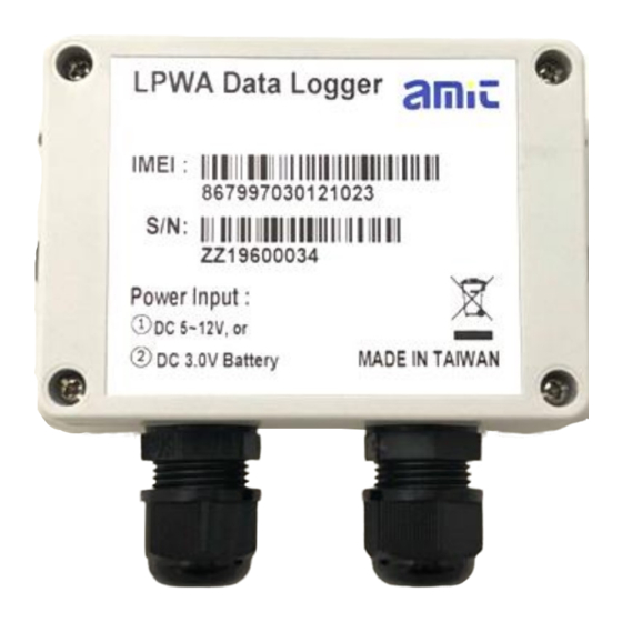
- Page 1 LPWA - LoRa Outdoor LoRa Data Logger OOT550-DL3B2 User Manual...
-
Page 2: Table Of Contents
Outdoor LoRa Data Logger Chapter 1 Introduction ............................3 1.1 Introduction .............................. 3 1.2 Contents List ............................4 1.2.1 Package Contents ........................... 4 1.3 Hardware Configuration .......................... 5 1.4 LED Indication ............................6 1.5 Installation & Maintenance Notice ......................7 1.5.1 SYSTEM REQUIREMENTS ....................... -
Page 3: Chapter 1 Introduction
Outdoor LoRa Data Logger Chapter 1 Introduction 1.1 Introduction Congratulations on your purchase of this outstanding product: Outoor LoRa Data Logger. For IIoT applications, AMIT LoRa Data Logger is absolutely the right choice. With built-in world-class LoRaWAN module, you can easily deploy the LoRa Data Logger with LoRaWAN compliant LoRa Gateway / NS / AS for a public or private LoRaWAN service. -
Page 4: Contents List
Outdoor LoRa Data Logger 1.2 Contents List 1.2.1 Package Contents #Standard Package Items Description Contents Quantity OOT550-DL3B2 1pcs Outdoor LoRa Data Logger Battery 1pcs Cable Tie 2pcs AI Jumper 3pcs Water/Dust-proof Stopper 3pcs... -
Page 5: Hardware Configuration
Outdoor LoRa Data Logger 1.3 Hardware Configuration Front View M16 Water/Dust-proof Connectors, with two-hole cable gland inserted... -
Page 6: Led Indication
Outdoor LoRa Data Logger 1.4 LED Indication LED Color LED Icon Indication Description Steady OFF: Device is powered off. Blue Flash per second: Device is boot up. Device Status Blue / Red Red Flash: Battery Low. Blue and Red Steady ON: Device is in Recovery mode, or FW Upgrading. -
Page 7: Installation & Maintenance Notice
Outdoor LoRa Data Logger 1.5 Installation & Maintenance Notice 1.5.1 SYSTEM REQUIREMENTS LoRaWAN compliant Gateway and Network Server Network Requirements Computer with the following: Windows®7 or Windows 10 An installed Ethernet adapter Configuration Tool Requirements A USB 2.0, or later for device configuration 1.5.2 WARNING Only use the Battery that comes with the package or ... - Page 8 Outdoor LoRa Data Logger Federal Communication Commission Interference Statement This device complies with Part 15 of the FCC Rules. Operation is subject to the following two conditions: (1) This device may not cause harmful interference, and (2) this device must accept any interference received, including interference that may cause undesired operation.
-
Page 9: Product Information For Ce Red Requirements
Outdoor LoRa Data Logger 1.5.4 Product Information for CE RED Requirements The following product information is required to be presented in product User Manual for latest CE RED requirements. (1) Frequency Band & Maximum Power 1. Frequency Band for LoRa Connection Band Operating Frequency Max. -
Page 10: Hardware Installation
Outdoor LoRa Data Logger 1.6 Hardware Installation Hereunder list the available H/W ports of OOT550: • SIM Slot: 1* nano-SIM (4FF) • Analog Input: 3* AI ports (AI1,AI2 supports 0-10V / 4-20mA; AI3 supports 0-20V / 0-40mA) • Digital Input: 2* DI ports (isolated, “Logic 1”: 2V~25V, “Logic 0”: 0~1V or floating;... - Page 11 Outdoor LoRa Data Logger Internal View After removed the top cover, you can see all the available hardware connectors. Nano-SIM RESET Power Switch Status Console for Micro-USB for Antenna (ON/OFF) Socket Button Device Config. Device Config. Cable (reserved) (reserved) CON2: CON4: CON1:...
-
Page 12: Install Battery
Outdoor LoRa Data Logger 1.6.2 Install Battery Step 1: Insert the two cable ties and go through the battery stands. Step 2: Load the battery over the stands as the illustrated, and pull tightly for each cable tie. - Page 13 Outdoor LoRa Data Logger Step 3: Cut off the extra cable tie, and plug the power cable onto CON1 (Battery Power Socket). WARNING : 1. It is strictly forbidden to have the battery positive and negative short circuit, charging, discharging, heating over 100 ℃, remove, anatomy, or may cause explosion, combustion, internal acid leakage.
- Page 14 Outdoor LoRa Data Logger Li-SOCL2 Battery Specification If you purchase the battery from 3rd-party, please make sure it comply to the following electrical characteristics. Not only Nominal Capacity and Voltage, but also Max. Continuous Current andf Max. Pulse Capacity specifications are important.
-
Page 15: Connecting To External Devices
Outdoor LoRa Data Logger 1.6.3 Connecting to External Devices There are lots of available I/O interfaces for connecting the OOT550 data logger with external devices. As indicated in the I/O pinout sheet, you can easily find out the pin location and connect to your devices with appropriate conductive cables. - Page 16 Outdoor LoRa Data Logger Run External cable to desired Connectors: Step 1: a) Find a conductive cable with 15mm tinned terminals; b) Remove the external part of the M16 connector; c) Run the cable through the external parts as indicated below. Step 2: a) Place the tinned terminal over the connector;...
- Page 17 Outdoor LoRa Data Logger Screw back the External Parts of M16 Connector: When you complete all the required hardware and software installation, and make sure it can work as what you planned. You are ready to lock the cables and external parts of the M16 connectors. Step 1: a) Just keep required length of cable inside the enclosure;...
- Page 18 Outdoor LoRa Data Logger Connect to devices via AIs (Analog Input) : The OOT550 provides 3 AI ports for connecting to those analog sensor/meters. To connect the device, you have to identify the type of your device and properly connect and configure the OOT550 so that it can get the correct readings from the connected devices.
- Page 19 Outdoor LoRa Data Logger Example of AI Connection Diagram If the signal range of your device will run out off the design spec. of OOT550, you have to add a certain scaling circuit to prevent overflow readings and even damage the OOT550.
- Page 20 Outdoor LoRa Data Logger Connect to devices via DIs / DO (Digital Input / Digital Output) : The OOT550 provides 2 DI ports and 1 DO port for connecting to those digital sensor/meter devices. To connect the device, you have to identify the type of your device and properly connect and configure the OOT550 so that it can get the correct readings from the connected devices.
- Page 21 Outdoor LoRa Data Logger Example of Connection Diagram - DO...
- Page 22 Outdoor LoRa Data Logger Connect to Modbus RTU devices via RS-485 : The OOT550 provides 1 RS-485 port and can support up to 3 cascaded Modbus RTU devices. Since the OOT550 can not detect what kind of device is connected to, not only hardware configuration (CON2) is required, but also software configuration is mandatory.
- Page 23 Outdoor LoRa Data Logger Connect to external DC Power Source: OOT550 is designed with internal Battery Power source. It is suitable for the situation for not frequently data logging or data uploading applications. However, there is an alternative external DC Power Source for those applications required instantly or frequently data uploading.
-
Page 24: Connecting Usb Cable For Pc Configuration Tool
Outdoor LoRa Data Logger 1.6.4 Connecting USB cable for PC Configuration Tool After completing prior hardware configuration, you are almost finishing the hardware configuration procedure. To make the OOT550 operate properly in according to attached external devices, you have to further configure software settings from a PC configuration tool. -
Page 25: Power On The Oot550
Outdoor LoRa Data Logger 1.6.5 Power On the OOT550 Congratulation! You have just finished the required hardware installation procedure, and you are ready to power on the OOT550. Please make sure the power source is properly installed: For Battery Power : Battery power cable is plugged onto the Power Socket (CON1);... - Page 26 Outdoor LoRa Data Logger Now, you can power on the OOT550 with Power Switch (S2). Switch it to the lower side (ON) and the OOT550 is powered on and start to boot up. Then you can check the Status LED, it starts with RED light(LED1) and BLUE light(LED2) for 1~2 seconds. After a while, LED1 and LED2 will turn to OFF state , and the device is booting up.
-
Page 27: Setup With Windows-Based Configuration Tool
Outdoor LoRa Data Logger 1.6.6 Setup with Windows-based Configuration Tool The OOT550 series product has to be configured with a Windows configuration tool. Just find out a PC/NB with an available USB port, and plug in the USB cable into it. For the first time to setup the OOT550 with his Configuration Tools, you have to download it from the vendor provided URLs or QR-code, and install it to the PC/NB for further device configuration. - Page 28 Outdoor LoRa Data Logger power consumption consideration. 2.Or, if DC Power Source is not available at the installation site, you are suggested to configure the device with a prepared configuration file to prevent unexpected battery power loss. Restore the prepared configuration file, and quickly edit the settings unique to a certain device.
-
Page 29: Device Mount And Screw Back The Top Cover
Outdoor LoRa Data Logger 1.6.7 Device Mount and Screw Back the Top Cover The OOT550 series product has to be configured with a Windows configuration tool. Just find out a PC/NB with an available USB port, and plug in the USB cable into it. After you finished all the software configurations, you are ready to free the OOT550 and make it operate as expected. -
Page 30: Chapter 2 Device Configuration
Outdoor LoRa Data Logger Chapter 2 Device Configuration 2.1 Device Status Click on Status menu item, and the OOT550’s device information and status will display on configuration area which is located in the right-hand side. If the device status doesn’t appear or you want to get the updated status, click Status Refresh button located at the lower right corner to refresh the status immediately. -
Page 31: Lora Configuration
Outdoor LoRa Data Logger 2.2 LoRa Configuration In the LoRa Configuration page, you can configure the channel, activation settings and MAC Layer settings. Channel Configuration There are Channel Group 1 and 2. It will show the supported Sub-Band depend on the area of the LoRa specification. - Page 32 Outdoor LoRa Data Logger Activation Configuration Prior to connect the LoRa Node to a certain LoRaWAN Network Server, you can configure device activation settings for how it connect to the network and how the remote geteway and network server can identify the LoRa Node.
- Page 33 Outdoor LoRa Data Logger Activation: Specify the desired actication method for the LoRa node to connect to a network. OTAA (Over-the-Air Activation) and ABP (Activation by Personalization) are supported. By default, ABP is selected. OTAA: OTAA is the preferred and most secure way to connect with network server. Devices perform a join-procedure with the network server, during which a dynamic Device Address is assigned and security keys (Network Session Key, APP Session Key) are negotiated with the device.
- Page 34 Outdoor LoRa Data Logger Get Data Interval: Specify the time interval which the node will get the status of connected sensor/meters on every designed time interval. By default, 300 seconds is configured. Finally, click Save button to store the configuration in the device. Note: DO NOT choose the Class C device type while it is powered by internal battery.
-
Page 35: I/O Configuration
Outdoor LoRa Data Logger 2.3 I/O Configuration In the I/O Configuration screen, you can configure the Analog Inputs (AIs) and Digital Inputs (DIs). There are 3 sets of AIs and 2 sets of DIs. According to the hardware configuration you already finished, you have to further configure the settings for the device firmware, so that the Data Logger will know what kind of input device is connected to each port. - Page 36 Outdoor LoRa Data Logger Offset: Enter the Offset value for initial reading of the connected device (pulse meter). It is very likely that the initial reading for the connected device is a non-zero value, so you have to enter the initial value as an offset for the further readings. With the settings, the Data Logger will activate 32-bit counters to count the pulse behavior, record the counter value plus the Offset as the actual value on each data logging time slot.
- Page 37 Outdoor LoRa Data Logger For the data logger with battery power option, there is a Battery Threshold configuration. You can define the Battery Full and Battery Low voltage. You can check the battery status at the Status Page. Full: for voltage >= Battery Full threshold. Good: for voltage between Battery Full and Low thresholds.
-
Page 38: Modbus Configuration
Outdoor LoRa Data Logger 2.4 Modbus Configuration The OOT550 series product provides one RS-485 port for connecting with Modbus RTU Slave devices. It can handle up to three sets of cascaded Modbus devices. RS-485 Serial Port Configuration Prior to configure how to access the Modbus devices, you need to define the physical communication port first. - Page 39 Outdoor LoRa Data Logger Name: Enter a name as the identifier of the Modbus RTU slave device. Slave ID: Specify a unique ID for the slave device. It can be 1 - 247. Function Code: Specify a certain read function for the Data Logger to issue and record the responses from slave device.
-
Page 40: Event Configuration
Outdoor LoRa Data Logger 2.5 Event Configuration The Event Trigger function can use a certain input signal (device) as trigger source for an event rule. If there is any enabled event rule, the data logger will check the trigger source once per second to determine event trigger or not. - Page 41 Outdoor LoRa Data Logger Cond.1/2: Up to two conditions can be defined in an event rule. For each condition, five comparison operators. “>”,”>=”,”=”,”<” and “<=” can be selected. Select an operator and enter a threshold value for comparison. Value1/2: Enter the threshold value of condition 1/2 for comparison. Operation: If cond.2 exists, specify the logic operation (AND, OR) for cond.1 and cond.2.
-
Page 42: System Configuration
Outdoor LoRa Data Logger 2.6 System Configuration System Configuration allows the device administrator / installer to manage the Data Logger. There are settings / function buttons for Reboot, Reset to Default, Configuration Backup / Restore, System Log, Firmware Upgrade, System Time, and Sleep Mode. Reboot or Reset to Default For some special reason or situation, you may need to reboot the Data Logger or reset the device configuration to its default value. - Page 43 Outdoor LoRa Data Logger System Log For some device maintenance purpose, you may need to get the system log for troubleshooting. You can do it through the configuration tool, click Download or Delete button. Click Download button to store the System Log into a log file (.txt) for troubleshooting. Click Delete button to erase the existing system logs.
-
Page 44: Cli Console Log
Outdoor LoRa Data Logger 2.7 CLI Console Log The system console log will show at this configuration page. It can help to monitor the system operation and event. When some issue happens, capture this console log and consult with device vendor. -
Page 45: Chapter 3 Commands For The Lora Node
Outdoor LoRa Data Logger Chapter 3 Commands for the LoRa Node The OOT550-DL is a LoRaWAN compliant LoRa node. With proper configuration, it can automatically send out (report) the status (data) of all the connected meter/sensors to a registered LoRa Network Server through a certain LoRaWAN gateway(s) at a designated time interval. - Page 46 Outdoor LoRa Data Logger for(i=0; i<len; i++){ ret ^= buf[i]; return ret;...
-
Page 47: Commands
Outdoor LoRa Data Logger 3.2 Commands 0x01 – Report all Inputs: 0x01 Total length Data[i] length Data[i] value[] … Checksum 1 byte 1 byte 1 byte n byte 1 byte Command: 0x01 Purpose: A LoRa node is Uploading the status (data) of all input ports to network server. Sequence: DI[1] / DI[2] / AI[1] / AI[2] / AI[3] / Modbus[1] / Modbus[2] / Modbus[3] Note 1: There is maximum limit on the payload size. - Page 48 Outdoor LoRa Data Logger 0x02 – Report all Enabled Inputs: 0x02 Total Port ID[i] Data[i] Data[i] … Checksum length length value[] 1 byte 1 byte 1 byte 1 byte 1 byte * n 1 byte Command: 0x02 Purpose: A LoRa node is Uploading the status (data) of all enabled input ports to network server. Port ID[i]: Identifier for each input port.
- Page 49 Outdoor LoRa Data Logger 0x03 – Report each Enabled Input: 0x03 Total Port ID[i] Data[i] Data[i] … Checksum length length value[] 1 byte 1 byte 1 byte 1 byte 1 byte * n 1 byte Command: 0x03 Purpose: A LoRa node is Uploading the status (data) of all enabled input ports to network server. Similar to 0x02, but due to payload limitation issue on low data rate connection, up to 4 separate packets could be transmitted.
- Page 50 Outdoor LoRa Data Logger 0x81 – Get all Inputs: 0x81 Total length Checksum 1 byte 1 byte 1 byte Command: 0x81 Purpose: A network server is asking for the LoRa node to get the status (data) of all input ports. Note 1: There is maximum limit on the payload size.
- Page 51 Outdoor LoRa Data Logger 0x82 – Get all enabled Inputs: 0x82 Total length Checksum 1 byte 1 byte 1 byte Command: 0x82 Purpose: A network server is asking for the LoRa node to get the status (data) of all enabled input ports. For example, the packet“820280”...
- Page 52 Outdoor LoRa Data Logger 0x84 – Set Value: 0x84 Total length Device ID Data length Datavalue[] … Checksum 1 byte 1 byte 1 byte 1 byte 1 byte * n 1 byte Command: 0x84 Purpose: A network server is asking for the LoRa node to set the value (data) of specific enabled output port. Device ID: Identifier for each outout port.
- Page 53 Outdoor LoRa Data Logger 0x70 – Low Power Warning: 0x70 Total length Checksum 1 byte 1 byte 1 byte Command: 0x70 Purpose: A LoRa node is alerting to the network server with low battery power warning. For example, the packet“700272” is composed of Command byte –...
Need help?
Do you have a question about the OOT550-DL3B2 and is the answer not in the manual?
Questions and answers