Table of Contents
Advertisement
Available languages
Available languages
RECTANGULAR GAS FIREPIT
RECTANGULAR CALENTADOR DE
OWNER'S MANUAL / MANUAL DEL PROPIETARIO
GUARDE ESTE MANUAL PARA REFERENCIA FUTURA
NOTICE TO INSTALLER:
LEAVE THESE INSTRUCTIONS
WITH THE FIREPIT OWNER FOR
FUTURE REFERENCE.
AVISO PARA EL
INSTALADOR:
ENTREGUE ESTAS
INSTRUCCIONES AL
PROPIETARIO DE EL
CALENTADOR DE FUEGO PARA
REFERENCIA FUTURA.
FUEGO A GAS
ASSEMBLY AND OPERATING INSTRUCTIONS
INSTRUCCIONES DE ARMADO Y OPERACIÓN
SAVE THIS MANUAL FOR FUTURE REFERENCE
HAZARDOUS EXPLOSION MAY RESULT IF THESE WARNINGS AND INSTRUCTIONS
ARE IGNORED. READ AND FOLLOW ALL WARNINGS AND INSTRUCTIONS IN THIS
MANUAL TO AVOID PERSONAL INJURY, INCLUDING DEATH OR PROPERTY DAMAGE.
SE PUEDE PRODUCIR UNA EXPLOSIÓN PELIGROSA SI SE HACE CASO OMISO A
ESTAS ADVERTENCIAS E INSTRUCCIONES. LEA Y SIGA TODAS LAS ADVERTENCIAS
E INSTRUCCIONES EN ESTE MANUAL PARA EVITAR LESIONES PERSONALES,
FOR OUTDOOR USE ONLY
SOLO PARA USO AL AIRE LIBRE
WARNING/ADVERTENCIA
INCLUSO LA MUERTE, O LOS DAÑOS MATERIALES.
Advertisement
Chapters
Table of Contents

Subscribe to Our Youtube Channel
Summary of Contents for Charmglow Gas FirePit
- Page 1 RECTANGULAR GAS FIREPIT RECTANGULAR CALENTADOR DE OWNER’S MANUAL / MANUAL DEL PROPIETARIO ASSEMBLY AND OPERATING INSTRUCTIONS INSTRUCCIONES DE ARMADO Y OPERACIÓN SAVE THIS MANUAL FOR FUTURE REFERENCE GUARDE ESTE MANUAL PARA REFERENCIA FUTURA NOTICE TO INSTALLER: LEAVE THESE INSTRUCTIONS WITH THE FIREPIT OWNER FOR FUTURE REFERENCE.
-
Page 2: Important Safety
IMPORTANT SAFETY WE WANT YOU TO ASSEMBLE AND USE YOUR FIREPIT AS SAFELY AS POSSIBLE. THE PURPOSE OF THIS SAFETY ALERT SYMBOL ATTENTION TO POSSIBLE HAZARDS AS YOU ASSEMBLE AND USE YOUR FIREPIT. WHEN YOU SEE THE SAFETY ALERT SYMBOL PAY CLOSE ATTENTION TO THE INFORMATION WHICH FOLLOWS! READ ALL SAFETY WARNINGS AND INSTRUCTIONS CAREFULLY BEFORE ASSEMBLING AND OPERATING YOUR FIREPIT. -
Page 3: Table Of Contents
TABLE OF CONTENTS Important Safety Information ........3 Firepit Specifications . -
Page 4: Important Safety Information
Always place the firepit on a firm and level surface. • Solid fuels shall not be burned in this gas firepit. • The firepit shall be used only outdoors in a well-ventilated space and shall not be used in a building, garage or any other enclosed area. -
Page 5: Lp Gas Cylinder
DO NOT connect to a cylinder that uses any other type of valve connection device. CYLINDER SPECIFICATIONS: When purchasing or exchanging a cylinder for your gas firepit, it must be constructed and marked in accordance with the specifications for LP gas cylinders of the U.S. Department of Transportation (DOT) or the National Standard of Canada, CAN/CSA-B339 Cylinders, Spheres and Tubes for Transportation of Dangerous Goods;... - Page 6 • Turn off the cylinder valve when your firepit is not in use. • Handle the tank with care. • Always secure the cylinder in an upright position. • Never connect an unregulated LP gas cylinder to your firepit. • DO NOT expose LP gas cylinders to excessive heat or ignition sources.
-
Page 7: Hose And Regulator
FILLING THE LP GAS CYLINDER: • Allow only qualified LP gas dealers to properly fill or repair your LP gas cylinder. • New tanks should be purged prior to filling; inform LP gas dealer if you are using a new tank. •... - Page 8 Never use your firepit without leak testing all gas connections and hoses. See the section on "Leak Testing" in this manual for proper procedures. The pressure regulator and hose assembly supplied with your gas firepit must be used. • DO NOT attempt to connect it to any other fuel supply source such as a natural gas line.
-
Page 9: Checking For Leaks
LEAK TESTING: To prevent fire or explosion hazard: • DO NOT smoke or permit ignition sources in the area while conducting a leak test. • Perform test OUTDOORS only in a well ventilated area. • Never perform a leak test with a match or open flame. •... -
Page 10: Pre-Start Check List
6. Check each place listed (A– K) for growing bubbles which indicates a leak. 7. Turn off gas supply at cylinder valve. 8. Turn on the control knob to release gas pressure in hose. 9. Turn the control knob to "OFF" position. 10. -
Page 11: Lighting Instructions
Read, understand and follow all warnings and instructions contained in this manual. DO NOT skip any of the warnings and instructions contained in the preceding sections of this manual. LIGHTING INSTRUCTIONS: Follow the instructions exactly. 1. REMOVE THE FIREPIT COVER before attempting to light the burner so that gas fumes do not accumulate inside the firepit. -
Page 12: Storage And Maintenance
TURNING OFF THE GAS FIREPIT: 1. Turn off the cylinder valve. 2. Turn burner control knob to the "OFF" position. Note: Turn off LP cylinder first to prevent gas from being left in the system under pressure. CAUTION: • The cylinder valve should always be in the off, or closed, position when the firepit is not in use. -
Page 13: Trouble Shooting
TROUBLE SHOOTING PROBLEM OBSERVED Gas odor Delayed ignition Incorrect burner flame POSSIBLE CAUSE Gas leakage Low gas pressure Clogged or dirty burner ports Bad battery Incorrect gas supply or pressure Clogged or dirty burner ports CORRECTIVE MEASURES Check all gas connections Check gas supply pressure Clean burner ports-see manual section Change battery... -
Page 14: Parts Bag Contents
PARTS BAG CONTENTS Make sure you have all items listed under PARTS LIST and PARTS BAG CONTENTS before you begin the installation process. Your Parts Bag will include: Qty. 34 M6 X 14mm Bolts M5 Washer M6 Washers M4 X 30mm Bolts M5 Washer M6 Washers Qty. -
Page 15: Assembly Instructions
Front & Back Table Panels Right Side Panel Back Side Panel FOR FIREPIT WARRANTY REPLACEMENT PARTS, PLEASE VISIT US AT: www.grillpartsonline.com ® Rectangular Gas Firepit: Front Side Panel Left Side Panel Tank Holder Support Strengthener Supports Sliding Tracks Connection Tube... - Page 16 Choose a good, cleared assembly area and get a friend to help you to unpack and set up your firepit. CAUTION: Some parts may contain sharp edges. Wear protective gloves if necessary. Step 1 Attach the four table panels by using eight M6 x14mm bolts and eight M6 washers.
- Page 17 Step 5 Connect the drawer panel with the tank holder support by using four M6 x 14mm bolts. Attach both strengthener supports to the drawer panel and tank holder support by using four M6 x 14mm bolts. Insert cylinder clamp screw as shown. Cylinder Clamp Screw Note: With the help of a friend, turn...
- Page 18 Step 7 Align tank holder support runners with the sliding tracks on the front and rear panels. Insert runners fully until locked into position. Step 8 Place the burner assembly on the table with the control panel facing the front panel door, attach it by using four M4 x 30mm bolts.
- Page 19 Firepit Cover Lava Rocks Firepit Grate Battery Compartment Battery Step 9 Insert cover handle through firepit cover and secure it to cover by using one M5 washer and M5 nut. Step 10 Place firepit grate directly over burner assembly. Step 11 Arrange lava rocks on firepit grate.
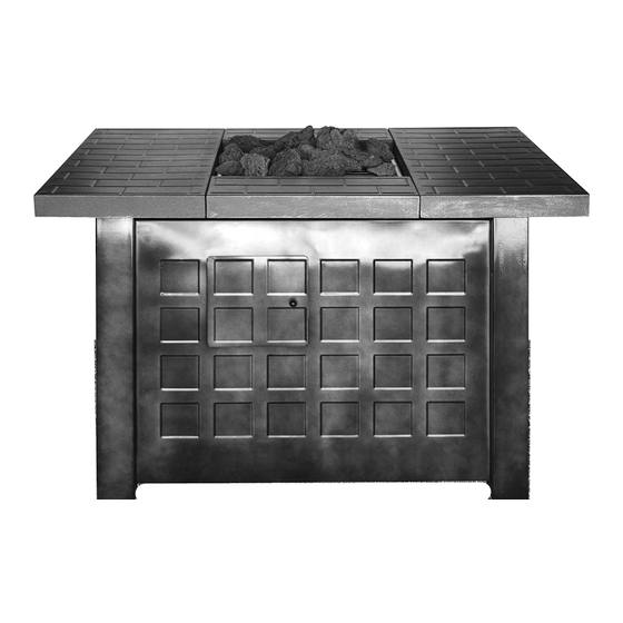
- Page 20 ® Charmglow Rectangular Gas Firepit (Assembled)
-
Page 21: Importantes Advertencias De Seguridad
IMPORTANTES ADVERTENCIAS ES NUESTRO DESEO QUE ARME Y UTILICE SU CALENTADOR DE LA FORMA MÁS SEGURA POSIBLE. EL PROPÓSITO DE ESTE SÍMBOLO DE ALERTA DE SEGURIDAD ES QUE USTED PRESTE ATENCIÓN A LOS POSIBLES PELIGROS CUANDO ARME Y UTILICE SU CALENTADOR. ¡CUÁNDO VEA ESTE SÍMBOLO DE ALERTA DE SEGURIDAD ESPECIAL A LA INFORMACIÓN A CONTINUACIÓN! LEA DETENIDAMENTE TODAS LAS ADVER TENCIAS DE SEGURIDAD E... - Page 22 Información Importante de Seguridad ......22 Especificaciones para Calentador ....... . . 23 Especificaciones / Instalación para Cilindro de propano líquido .
-
Page 23: Información Importante De Seguridad
INFORMACIÓN IMPORTANTE DE SEGURIDAD • La instalación debe conformarse con códigos locales o, en ausencia de códigos locales, con el Código Nacional del Combustible, “National Fuel Code, ANSI Z223.1.” • El aparato, cuando instalado, debería estar aterrizado eléctricamente en conformidad con códigos locales o, en ausencia de códigos locales, con El Código Eléctrico Nacional, “The National Electrical Code, ANSI/NFPA70.”... -
Page 24: Especificaciones Para Calentador
ESPECIFICACIONES PARA CALENTADOR RECTANGULAR A GAS: Nombre de Producto No. de Modelo Producción de Calor Combustible Suministro de Gas Presión de Colector Tamaño de Orificio (diámetro) Presión de Suministro de Gas CILINDRO DE GAS DE PROPANO LÍQUIDO El cilindro de propano líquido puede comprarse en el mismo lugar donde compró el calentador. El cilindro de gas de propano líquido diseñado específicamente para usarse con este calentador debe tener una capacidad de 20 libras (9,1 kg) e incorporar una válvula de cilindro tipo 1 y un dispositivo de protección contra el llenado excesivo (OPD). - Page 25 • Apaga la válvula del cilindro cuando su calentador no está en uso. • Maneja el tanque con el cuidado. • Siempre asegure el cilindro en una posición vertical. • Nunca conecte un cilindro de gas de propano líquido no regulado a su calentador. •...
-
Page 26: Manguera Y Regulador
LLENANDO EL CILINDRO DE GAS DE PROPANO LÍQUIDO: • Sólo los distribuidores de gas de propano líquido capacitados deben llenar o reparar su cilindro. • Los tanques nuevos deben ser purgados antes de llenarlos; dígale al distribuidor de gas si está usando un tanque nuevo. - Page 27 NO use ningún otro conjunto de regulador de presión/manguera que no sea el suministrado con el calentador. El número de parte del conjunto de regulador de presión/manguera de repuesto debe ser Brinkmann Nº 155-2400-0 y puede obtenerse comunicándose con Brinkmann al 800-527-0717. •...
-
Page 28: Pruebas De Detección De Fugas
PRUEBAS DE DETECCIÓN DE FUGAS: Para impedir los peligros de incendio o explosión: • NO fume ni permita que haya fuentes de encendido en el área mientras realiza la prueba de detección de fugas. • Realice la prueba AL AIRE LIBRE únicamente, en un área bien ventilada. •... -
Page 29: Lista De Verificación Preliminar Al Encendido
6. Inspeccione cada uno de los elementos indicados (A-K) para ver si hay burbujas, lo cual indica una fuga. 7. Cierre el suministro de gas en la válvula del cilindro. 8. Gire las perillas de control para descargar la presión de gas en la manguera. 9. -
Page 30: Instrucciones De Encendido
Lea, entienda y siga todas advertencias y las instrucciones contenidas en este manual. NO OMITA cualquiera de las advertencias e instrucciones en las secciones anteriores de este manual. INSTRUCCIONES DE ENCENDIDO: Siga las instrucciones al pie de la letra. REMUEVA LA CUBIERTA DE EL CALENTADOR ANTES de intentar encender el quemador asi los vapores de gas no se acumulan dentro del calentador. -
Page 31: Cuidado Y Mantenimiento Apropiados
APAGANDO EL CALENTADOR : 1. Cierre la válvula del cilindro. 2. Gire la perilla de control de la hornilla a la posición "OFF" (apagado). Nota: Apague el cilindro de propano líquido primero para evitar que quede gas en el sistema bajo presión. -
Page 32: Identificación Y Corrección De Problemas
IDENTIFICACIÓN Y CORRECCIÓN DE PROBLEMAS PROBLEMA Olor de gas Ignición demorada Llama de quemador incorrecta CAUSAS POSIBLES Fuga de gas Suministro bajo de gas Quemador atascado Batería gastada El suministro inexacto de gas Quemador atascado MEDIDAS CORRECTIVAS Verifique todas conexiones de gas Cheque la presión de gas Limpie quemadores - vea section de manual... - Page 33 CONTENIDO DE LA BOLSA DE PARTES Verifique que tiene todos los artículos indicados en la LISTA DE PARTES y en el CONTENIDO DE LA BOLSA DE PARTES antes de comenzar con el proceso de instalación. La bolsa de partes incluirá lo siguiente: Qty.
-
Page 34: Instrucciones De Armado
INSTRUCCIONES DE ARMADO LEA DETENIDAMENTE TODAS LAS ADVERTENCIAS DE SEGURIDAD E INSTRUCCIONES ANTES DE ARMAR Y USAR EL CALENTADOR RECOMENDAMOS QUE ESTA UNIDAD SEA ARMADA POR DOS PERSONAS Se necesitan las siguientes herramientas para armar este calentador rectangular de fuego a gas: •... - Page 35 Panel Frontal y Trasero para Mesas Panel Derecho e Izquierdo para Mesas Panel Trasero Lateral Elija un lugar adecuado y despejado para armar la parrilla y pídale a un amigo que le ayude. CUIDADO: Algunas partes pueden Paso 1 Ate los cuatro paneles para la mesa utilizando ocho pernos M6 x14mm y ocho arandelas M6.
- Page 36 Paso 5 Conecte el panel del portatanque con el portatanque utilizando cuatro pernos M6 x 14mm. Ate el reforzado para soportes así como el panel del potatanque y el portatanque juntos utilizando cuatro pernos M6 x 14mm. Inserte el tornillo de abrazadera para el cilindro como mostrado.
- Page 37 Paso 7 Alinee corredores de apoyo del el portatanque con las vías deslizantes en los paneles frontal y trasero. Inserte corredores y métalos completamente hasta que se traben en posición. Paso 8 Coloque el asamblaje del quemador sobre la mesa con el tablero de control frente a la puerta frontal, átelo utilizando cuatro pernos M4 X 30 mm.
- Page 38 Paso 9 Inserte el asidero de cobertura del calentador y lo asegúrelo a la cobertura del calentador utilizando una arandela M5 y tuerca M5. Paso 10 Coloque la rejilla de calentador directamente sobre asamblaje del quemador. Paso 11 Arregle piedras de lava sobre la rejilla de calentador.
- Page 39 ® Charmglow Rectangular Calentador de Fuego a Gas (Armada)
-
Page 40: Warranty
Esta garantía se otorga al comprador original únicamente y no es transferible o asignable a los compradores posteriores. The Brinkmann Corporation exige un comprobante de compra razonable. Por lo tanto, le recomendamos enfáticamente que retenga su recibo o factura de venta.
Need help?
Do you have a question about the Gas FirePit and is the answer not in the manual?
Questions and answers