Table of Contents
Advertisement
Quick Links
4080051 / 2
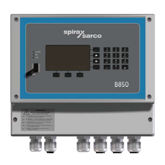
Boiler House Energy Monitor
B850-W-2
B850-P-2
IM-P408-04 AB Issue 2
B850-W-2 and B850-P-2
Quickstart Guide
2. Safety information
3. General product
and
delivery information
8. Mechanical installation
9. Electrical installation
10. Commissioning
15. Appendix
Please note that this is the 'Quickstart
Guide' and that all relevant Sections for
this product are contained in the main
Installation and Maintenance Instructions
IM-P408-03.
IM-P408-04
AB Issue 2
© Copyright 2015
1
Printed in Poland
Advertisement
Table of Contents

Related Manuals for Spirax Sarco B850-W-2

Summary of Contents for Spirax Sarco B850-W-2
- Page 1 4080051 / 2 IM-P408-04 AB Issue 2 B850-W-2 and B850-P-2 Boiler House Energy Monitor Quickstart Guide 2. Safety information 3. General product delivery information 8. Mechanical installation 9. Electrical installation 10. Commissioning B850-W-2 15. Appendix Please note that this is the 'Quickstart...
-
Page 2: Safety Information
2. Safety information Safe operation of this product can only be guaranteed if it is properly installed, commissioned, used and maintained by qualified personnel (see the following sections) in compliance with the operating instructions. General installation and safety instructions for pipeline and plant construction, as well as the proper use of tools and safety equipment must also be complied with. -
Page 3: Intended Use
Check that the product is suitable for use with the application. ii) Determine the correct installation situation. iii) Spirax Sarco products are not intended to withstand external stresses that may be induced by any system to which they are fitted. It is the responsibility of the installer to consider these stresses and take adequate precautions to minimise them. -
Page 4: Protective Clothing
2.11 Returning products Customers and stockists are reminded that under EC Health, Safety and Environment Law, when returning products to Spirax Sarco they must provide information on any hazards and the precautions to be taken due to contamination residues or mechanical damage which may present a health, safety or environmental risk. -
Page 5: All Rights Reserved
Certain computer programs contained in this product [or device] were developed by Spirax-Sarco Limited ('the Work(s)'). Copyright © Spirax-Sarco Limited 2015 All Rights Reserved Spirax-Sarco Limited grants the legal user of this product (or device) the right to use the Work(s) solely within the scope of the legitimate operation of the product (or device). -
Page 6: Receipt Of Shipment
1 x USB (Operating manual, configuration software) 1 x Carton package If it is found that some items have been damaged or are missing, notify Spirax Sarco immediately and provide full details. In addition, damage must be reported to the carrier with a request for their on-site inspection of the damaged item and its shipping carton. -
Page 7: Mechanical Installation
Note: Before actioning any installation observe the 'Safety information' in Section 2. B850 The B850 is available for wall mounting B850-W-2 or for panel mounting B850-P-2. Note: All versions must be fitted away from sources of excessive heat, electrical interference and from all areas liable to flooding. -
Page 8: Environmental Conditions
Be sure to allow sufficient clearance for: Installation of conduit / wiring. Viewing of the display. 8.1 Mounting instructions for the wall mounted B850-W-2: 1. Using the dimensions shown in Figure 13, drill 3 holes suitable for accepting 5 mm (No. 10) screws. - Page 9 Bottom mounting eyelet (access through the terminal compartment) Fig. 14 3. Fix an M5 (No. 10) screw to the surface for the top mounting. Leave the head of the screw proud of the surface, just enough to allow the top mounting lug of the B850 to slide over. Mounting screw left proud of surface to slot top mounting of B850 over.
- Page 10 8.2 Mounting instructions for the panel mounted B850-P-2: 1. A rectangle aperture 186 mm (7 ") wide x 92 mm (3 ") high is required to mount the panel mounted version of the B850 energy monitor. 2. Push the B850 through the aperture ensuring that the seal is fitted correctly. 3.
-
Page 11: Electrical Installation
7. Relay contacts must be supplied at the same phase as the product's mains supply. 8. The wall energy monitor (B850-W-2) is designed as an installation category product. 9. Wiring should be carried out in accordance with IEC 60364 or prevalent local standards. - Page 12 13. It is important that the cable screens are connected as shown in order to comply with the electromagnetic compatibility requirements. 14. To keep the integrity of the IP rating, consideration must be taken when planning the installation of the wiring between the B850 and the various sensors and meters. It is recommended that one or more electrical junction boxes are used.
- Page 13 Wall mounted B850-W-2 boiler house energy monitor 1 A fuse 100-240 Vac from supply Relay 1 (of 4) N / O Voltage free contacts Relay 1 (of 4) 30 Vdc 0.1 A Relay 1 (of 4) 240 Vac 3 A...
- Page 14 B850-W-2 Recommended inputs from Section 15, Appendix, IM-P408-03 IN 1 0 / 4 - 20 mA +24 V IN 1 ILVA flowmeter for steam (m bar or psi) IN 2 0 / 4 - 20 mA +24 V EL2600 pressure sensor...
- Page 15 Panel mounted B850-P-2 boiler house energy monitor 24 Vdc 8 W maximum Relay 1 (of 4) Relay 1 (of 4) Solid state relay 24 V 0.1 A RS-485 A(+) RS-485 Modbus B(-) RTU slave RS-485 Out 1 (of 2) 4 - 20 mA Out 1 (of 2) Output RJ-45...
- Page 16 B850-P-2 Recommended inputs from Section 15, Appendix, IM-P408-03 IN 1 0 / 4 - 20 mA +24 V IN 1 ILVA flowmeter for steam (m bar or psi) IN 2 0 / 4 - 20 mA +24 V EL2600 pressure sensor IN 2 for steam pressure, (bar g or psi g) IN 3...
- Page 17 10. Commissioning 10.19 B850 energy monitor commissioning using PC software for quick start-up The B850 energy monitor can be commissioned via the key pad on the front panel of the unit itself, or via separate PC software. The B850 is supplied with a USB memory stick which contains the PC software, product manuals and associated files.
- Page 18 10.20 Units and fuel selection A grey screen will appear. To create a new BEM configuration 'Click' on File / New Settings and select either imperial or metric units, a pop up will appear allowing you to choose your fuel type. This Quickstart IM has been written to be used in conjuction with the 'Gas-Quickstart' option, choose 'Custom' options if you requiring a different configuration.
- Page 19 Use the windows operating system to locate and load the desired configuration file. Select fuel type that the configuration was designed for and click OK. IM-P408-04 AB Issue 2...
- Page 20 10.21 BEM gas configuration quick start A partly configured BEM configuration will be presented. F G H I J K L M Main applications The process values and inputs have been partly pre-configured for the following applications: A. Steam output. B.
- Page 21 10.22 BEM configuration parameters The following table in conjunction with Sections 10.23 to 10.34 are the recommended order of stages for setting up the BEM. The table lists out the required values that will need to be entered into each stage. The table can be used as a check list and ticked off at each stages completion.
- Page 22 10.26 Inputs, continued from page 21 Tick when complete Value Units IN4 - 4 mA IN4 - 20 mA IN4 - Alarm IN4 - Other IN5 - 4 mA / h or ft IN5 - 20 mA / h or ft IN5 - Alarm IN5 - Other IN7 - Adjustment...
- Page 23 Continued from page 22 Tick when complete 10.29 Condensate return process values (page 32) Alarm Threshold Other 10.30 Fuel input (page 33) Alarm Other 10.30.2 Fuel input calculation (pages 34 - 35) Calorific Value 10.31 Blowdown and TDS (page 36) 10.31.1 Bottom blowdown calculation (pages 36 - 37) Flow co-efficient K v / C v...
-
Page 24: Steam Output
10.23 Steam output Click on main applications, the Steam Output application will be displayed. Enter Max F and coefficients from the flowmeter calibration certificate Set flowmeter size (this screen shot shows ILVA)* Set reference conditions, typically not required. Please refer to the flowmeter manual (in this case ILVA) for mechanical installation and pages 13 to 16 for the Wiring Diagrams. - Page 25 10.24 Feedwater Click on main applications, then B, the feedwater application will be displayed. Set reference conditions, typically not required. Please refer to the flowmeter manual (in this case ELM) for mechanical installation, and set up of its 4-20 mA output and pages 13 to 16 for the Wiring Diagrams. IM-P408-04 AB Issue 2...
-
Page 26: Condensate Return
10.25 Condensate return Click on main applications, then C, the condensate return application will be displayed. The nominal pressure must be determined and entered. Set reference conditions. Please refer to the flowmeter manual (in this case ELM) for mechanical installation, and set up of its 4-20 mA output and pages 13 to 16 for the Wiring Diagrams. - Page 27 10.26 Inputs Configure inputs. Assigned inputs to process values. Select input parameters Steam inputs input 2 for the steam pressure sensor, range 4-20 mA input, or may be configured for temperature sensor. A.Dp input 1 ILVA steam flowmeter, range 4-20 mA input. Feedwater inputs input 3 for the feedwater ELM flowmeter, range 4-20 mA input.
- Page 28 Range the 4 - 20 mA inputs for the flowmeters on inputs 1, 3, 4 and 5 and pressure sensor on input 1. Set Pt100 parameters for input 7 and 8. IM-P408-04 AB Issue 2...
- Page 29 Set ranges for BBD and TDS controller inputs on input 10 and 11. Valve Circuit Value Open closed Closed open PULS – type inputs: IN10, IN11 and IN12 may be set as '0' volt contacts for automated TDS Blowdown and Bottom Blowdown systems. Ensure voltage does not exceed 40 V. IM-P408-04 AB Issue 2...
- Page 30 10.27 Steam output process values Click on process values, and the steam output process values will be displayed. Click on the process values Thresholds (T), totalisers (t), alarms (A) and graph settings (G) can be set up for the Steam Output Process, for full details see B850 Boiler House Energy Monitor Installation and Maintenance Instructions IM-P408-03.
- Page 31 10.28 Feedwater process values Click on process values, then B, the feedwater process values will be displayed. Click on the process values Thresholds (T), totalisers (t), alarms (A) and graph settings (G) can be set up for the Feedwater Process, for full details see B850 Boiler House Energy Monitor Installation and Maintenance Instructions IM-P408-03.
- Page 32 10.29 Condensate return process values Click on process values, then C, the condensate return process values will be displayed. Click on the process values Thresholds (T), totalisers (t), alarms (A) and graph settings (G) can be set up for the Condensate Return, for full details see B850 Boiler House Energy Monitor Installation and Maintenance Instructions IM-P408-03.
- Page 33 10.30 Fuel input 10.30.1 Fuel input flowrate Click on process values, then X, the boiler efficiency calculation will be displayed. Click on the process values Thresholds (T), totalisers (t), alarms (A) and graph settings (G) can be set up for the Fuel Input Flowrate, for full details see B850 Boiler House Energy Monitor Installation and Maintenance Instructions IM-P408-03.
- Page 34 10.30.2 Fuel input calculation Click on the process values Thresholds (T), totalisers (t), alarms (A) and graph settings (G) can be set up for the Fuel Input Calculation, for full details see B850 Boiler House Energy Monitor Installation and Maintenance Instructions IM-P408-03. The Quickstart Configuration is pre-configured with suitable settings.
- Page 35 Calculation for Metric (kW) X.Qv*1/3600 A calorific value (CV) for the fuel must be entered into the calculation. Click on: Edit the '1' in the above calculation and add the calorific value for your fuel type. The calorific value (CV) must be entered in units of kJ / m Qv = Flowrate measured on Input 5 in m³...
- Page 36 10.31 Blowdown and TDS 10.31.1 Bottom blowdown calculation Click on process values 'Y' then Pb the BBD valve input calculation will then be displayed, input values required. Click on the process values Thresholds (T), totalisers (t), alarms (A) and graph settings (G) can be set up for the Bottom Blowdown Calculation, for full details see B850 Boiler House Energy Monitor Installation and Maintenance Instructions IM-P408-03.
- Page 37 Calculation for Metric (kW) Enthalpy Density ( Y.V b *1* 1*1* s q r t ((A . p D * 0 . 9)*10 0 0 / 1 )) 3600 Click on Edit each '1' in the above calculation to add the following values: Flow co-efficient - K v - Value must be taken from the technical documentation of the BBD Valve.
- Page 38 10.31.2 TDS calculation Click on process values 'Y' then Pt the BBD valve input calculation will then be displayed, input values required. Click on the process values Thresholds (T), totalisers (t), alarms (A) and graph settings (G) can be set up for the Bottom Blowdown Calculation, for full details see B850 Boiler House Energy Monitor Installation and Maintenance Instructions IM-P408-03.
- Page 39 Calculation for Metric (kW) Enthalpy Density ( Y.V t * 1*1*1 * s q r t ((A . p D * 0 . 9) *10 0 0 / 1 )) 3600 Click on Edit each '1' in the above calculation to add the following values: Flow co-efficient - K v - Value must be taken from the technical documentation of the BBD Valve.
-
Page 40: Boiler Efficiency
10.32 Boiler efficiency Click on process values, then Z, the boiler efficiency calculation will be displayed. Click on the process values Check / Select filter and set to 30 mins Thresholds (T), alarms (A) and graph settings (G) can be set up for the Boiler Efficiency, for full details see B850 Boiler House Energy Monitor Installation and Maintenance Instructions IM-P408-03. -
Page 41: Relay Outputs
10.33 Relay outputs Click on relay outputs. Four relay outputs can be configured. If you have set a requirement for a relay output in the threshold settings of Sections 10.27 - 10.32 you can set the relay activity, they can also be ascociated with Alarms. 10.34 Display screen settings Click on screen settings. - Page 42 10.35 4-20 mA output and other settings Click on relay outputs. Select required serial communication protocol (ASCII, GSM, Modbus RTU, BACnet) and parameters. Communication with a computer system. The unit can be connected to the master computer system by: Built-in serial RS-485 port; available is ASCII own protocol, Modbus RTU protocol and BACnet MSTP.
-
Page 43: Saving Your Configuration
10.36 Saving your configuration The configuration can now be saved. You can save to either the PC / laptop or memory stick if you require to configure the system further. Save the configuration onto the memory stick if you wish to load it onto the B850. C:\Users\user.name\Desktop\My Config It may be useful to limit your file name to 8 characters in length as the B850 will truncate longer file names when displaying them on its screen. - Page 44 10.37 Loading your configuration onto the B850 The configuration needs to be saved onto a suitable memory stick and the B850 powered up and operational. Remove the dust plug from the USB terminal on the front of the B850 and plug in the memory stick. →...
- Page 45 Click OK and the unit will restart with the configuration loaded. IM-P408-04 AB Issue 2...
-
Page 46: Process Values
15. Appendix 15.1 Process values List of process values used in the BEM: Application A (Section 10.23 and Section 10.27) Steam heat flowrate. Mass flowrate of steam. Volume flowrate of steam. Steam measured pressure (only for superheated or saturated steam with pressure measurement). - Page 47 15.2 Spare inputs Wall mounted B850-W-2 boiler house energy monitor IN 6 +24 V IN 6 0 / 4 - 20 mA input IN 6 IN 9 IN 9 IN 9 input IN 9 63 / 66 IN 12 PULSE...
- Page 48 15.3 Failure notification of measurement inputs Failures associated with particular channels are marked with appropriate symbols on the display. Symbols of failure: -F- RTD sensor failure. -||- 4-20 mA transducer failure, current below 3.6 mA. -E- 4-20 mA transducer failure, current above 22 mA. -S- steam parameters below saturation curve (only when detection of steam saturation is on).
Need help?
Do you have a question about the B850-W-2 and is the answer not in the manual?
Questions and answers