Table of Contents
Advertisement
Quick Links
Advertisement
Table of Contents

Summary of Contents for Lochinvar LOKE8-50
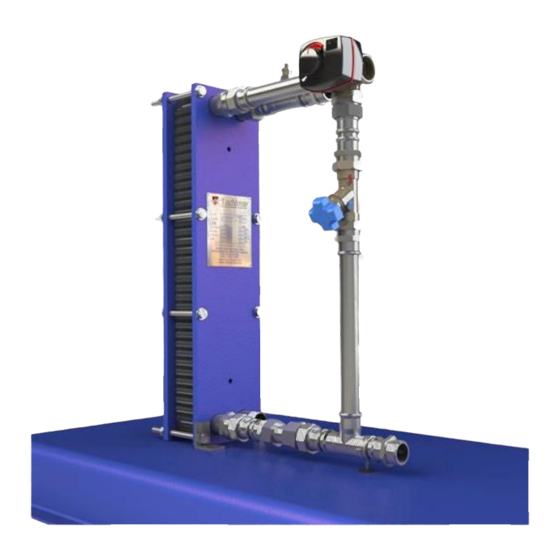
- Page 1 LOKE Instantaneous packaged plate heat exchanger Installation, Commissioning, Maintenance and User instructions Models LOKE8-50 LOKE8-75 LOKE8-100 LOKE8-125 LOKE8-150 LOKE8-175 LOKE8-200 LOKE8-225 LOKE8-250 installation manual_LOKE_November 2020...
- Page 2 BLANK PAGE...
-
Page 3: Table Of Contents
PRINCIPAL PARTS ..............................6 CONTROLLER ............................7 TECHNICAL DATA MODELS LOKE8-50 TO LOKE8-150..........................7 MODELS LOKE8-200 TO LOKE8-250 ..........................8 .......................... 9 DIMENSIONS AND CLEARANCE DIMENSIONS OF UNIT WITHOUT OPTIONAL BASE ......................9 DIMENSIONS OF UNIT WITH OPTIONAL BASE FITTED ....................10 CLEARANCES ................................ -
Page 4: Introduction
INTRODUCTION The Lochinvar LOKE Instantaneous packaged plate heat exchanger is designed to heat domestic hot water (DHW) using low temperature hot water (LTHW) from a boiler or similar. The unit is designed with a low return temperature during demand to ensure boilers are in continuous condensing mode. -
Page 5: General Description Of Safety Symbols Used
If there is a chance the peak demand could temporarily exceed the maximum flow rate of the unit chosen, then consideration should be given to using a small buffer vessel to cope with this peak flow. For help with sizing and selection please contact your local Area Sales Manager or Lochinvar Internal Sales. -
Page 6: Principal Parts
PRINCIPAL PARTS CONTROLLER Ambient temperature Max +55C Sensor Type NTC Ambient temperature Min Enclosure rating IP41 Temperature range +5 to + 95C Power supply 230V /1Ph/ 50hz Protection class Torque Power consumption 230v AC: 10VA Connection, mounting set External thread Running time at maximum speed 30seconds Supplied parts... -
Page 7: Technical Data Models Loke8-50 To Loke8-150
TECHNICAL DATA MODELS LOKE8-50 TO LOKE8-150 Output Unit LOKE8-50 LOKE8-75 LOKE8-100 LOKE8-125 LOKE8-150 Heat Transfer Duty Thermal efficiency 99.5 99.5 99.5 99.5 99.5 Primary Side Inlet Temperature °C Outlet Temperature °C Varies Depending on Demand (40 At Full Demand) Fluid Flow Rate litre/second 0.34... -
Page 8: Models Loke8-200 To Loke8-250
MODELS LOKE8-200 TO LOKE8-250 Output Unit LOKE8-175 LOKE8-200 LOKE8-225 LOKE8-250 Heat Transfer Duty Thermal efficiency 99.5 99.5 99.5 99.5 Primary Side Inlet Temperature °C Outlet Temperature °C Varies Depending on Demand (40 At Full Demand) Fluid Flow Rate litre/second 1.37 1.54 1.71 Fluid type... -
Page 9: Dimensions And Clearance
DIMENSIONS AND CLEARANCE Unit Dimension Total Height Depth Width DIMENSIONS OF UNIT WITHOUT OPTIONAL BASE... -
Page 10: Dimensions Of Unit With Optional Base Fitted
Unit Dimension Total Height Depth Width Base Depth DIMENSIONS OF UNIT WITH OPTIONAL BASE FITTED... -
Page 11: Clearances
CLEARANCES • Unit shown with optional base fitted, if unit does not have optional base clearances are from side of plate pack. • Side clearances can be reduced but the unit may need to be removed in the future if the plate pack requires replacing or cleaning... -
Page 12: Installation
INSTALLATION GENERAL REQUIREMENTS The LOKE water heater has been designed to operate trouble free for many years. These instructions should be followed closely to obtain the maximum usage and efficiency of the equipment. RELATED DOCUMENTS The installation of the equipment MUST be in accordance with the relevant requirements Building Regulations, I.E.E. Regulations and the bylaws of the local water undertaking. -
Page 13: Lifting
The Building Regulations: Part G3 in England and Wales, P5 in Northern Ireland and P3 in Scotland. A kit of components that have been suitably sized for the unvented or boosted operation of the appliance is available from Lochinvar Limited. For further... -
Page 14: Standard Un-Vented Kits
STANDARD UN-VENTED KITS LOK Model Part Number Description 22MM MONOBLOC INLET CONTROLS INCLUDES; NON-RETURN VALVE LOKE8-50 TO CLK3520 LOKE8-150 PRESSURE REDUCING VALVE - 3 TO 6 BAR 6 BAR PRESSURE RELIEF VALVE 28MM MONOBLOC INLET CONTROL INCLUDES: • NON-RETURN VALVE... -
Page 15: Schematics
Lochinvar limited may provide technical advice and guidance to assist with best practice, optimisation and installation of Lochinvar products; however, we will not be liable for any duties as designers under construction (design and management regulations 2015). In all cases where information is provided, the customer must assess and manage risks associated with the technical information and advice provided. - Page 16 Schematic LOKE instantaneous installation...
- Page 17 Schematic LOKE with storage vessel-schematic...
-
Page 18: 10.0 Electrical Supply
EXTERNAL CONTROLS There are no external control options with the LOKE unit, if a unit is required with BMS control options a standard LOK unit should be used, contact Lochinvar Internal sales for more information. -
Page 19: 11.0 Commissioning And Testing
11.0 COMMISSIONING AND TESTING WATER CONNECTIONS See Section 8.6: WATER CONNECTIONS The system should be thoroughly flushed out with cold water without any circulating pumps in position. Ensure all the valves are open. Check the system for leaks and repair as necessary. If the system is configured in a sealed arrangement, check the expansion vessel cushion pressure and pressurisation unit settings. -
Page 20: 12.0 Maintenance
12.0 MAINTENANCE MAINTENANCE SCHEDULE Time Interval Once a year as a minimum, every six months in hard water areas. Performance Check temperature and flow against commissioing data. Plate pack Check the tightening dimension, and look for any signs of leakage from heat exchanger. Connections Check general condition, and for any signs of leakage. -
Page 21: Cleaning Plate Gaskets
CLEANING PLATE GASKETS Instead of cleaning the plates, Lochinvar can supply a replacement plate pack. See spare parts finder at www.lochinvar.ltd.uk Wear gloves & eye goggles when using cleaning detergents Brushing: Use nylon or other types of “soft” scrubbing brushes with detergent. Never use a metal brush, steel wool, or sand/glass paper. -
Page 22: Procedure
Dimension A can be found within the plate sequencing sheet. 12.6.1 ASSEMBLY DIAGRAMS PROCEDURE Lightly oil the tie bolt threads. Evenly tighten all bolts. We recommend the use of ratchet / friction spanners. Ensure clamping is as uniform as possible, thus keeping the frames plates parallel throughout the operation. Avoid skewing the frame plates by more than 10mm. - Page 23 12.7.1 EXAMPLES OF GASKET AND PLATE TYPES...
-
Page 24: 13.0 Fault Finding
13.0 FAULT FINDING HEAT EXCHANGER PLATE PACK ASSEMBLY Nuts and fittings are tight to turn - insufficient oil on threads. Plates move out of alignment: remove plates & degrease, then dry, inspect plate hanging system for damage. EXCESSIVE PRESSURE DROPS Liquid flows higher than design: Check &... -
Page 25: 14.0 Declaration Of Conformity
14.0 DECLARATION OF CONFORMITY NOTES...
Need help?
Do you have a question about the LOKE8-50 and is the answer not in the manual?
Questions and answers