Table of Contents
Advertisement
Advertisement
Table of Contents

Related Manuals for Baltimore Aircoil Company NEXUS


Summary of Contents for Baltimore Aircoil Company NEXUS
- Page 1 OPERATION & MAINTENANCE MANUAL...
- Page 2 Recommended Maintenance Intervals Inspect and clean as necessary: Start-Up Monthly Quarterly Annually Shutdown Inspect general condition of the unit and check unit for unusual noise or vibration Inspect and clean the fan guard Inspect spray water basin and clean as required Inspect and flush water distribution system as required Check operation of solenoid make-up valve, mechanical make-up valve, and drain valve...
-
Page 3: Table Of Contents
Table of Contents OPERATION & MAINTENANCE » NEXUS™ MODULAR HYBRID COOLER Warnings and Cautions PART 4 Corrosion Protection Safety Precautions Water Treatment Equipment Precautions Corrosion and Scale Control General Maintenance Information Chemical Treatment Requirements Warranties Passivation Biological Control Alternative Water Sources PART 1 Start-Up &... -
Page 4: Safety Precautions
Safety Precautions DANGER DANGER: Rotating equipment will cause severe personal injury or death to persons who come in contact. Do not perform any service, maintenance, or inspection on or near the fan(s), motor(s), or inside the unit without first ensuring that the fans and pump motors are disconnected, locked out, and tagged out. -
Page 5: Equipment Precautions
Equipment Precautions NOTICE • BAC units are typically installed immediately after shipment and many operate year round. However, if the unit is to be stored for a prolonged period of time either before or after installation, certain precautions should be observed, as outlined in “Storage & extended Shutdown”... -
Page 6: Start-Up & Operation
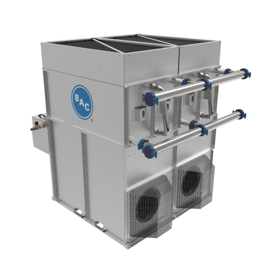
NEXUS™ MODULAR HYBRID COOLER Start-Up & Operation Figure 1. Nexus™ Modular Hybrid Cooler WWW. B A LT IM ORE A IRCOIL.COM... - Page 7 Start-Up and Operation 1. hCore™ Heat Transfer Technology: Exclusive closed loop heat transfer section with stainless steel construction that offers high corrosion-resistance. Nexus™ Modular Hybrid Cooler 2. Fluid Connections: Fewest field piping connections due to innovative, easy-to-install manifold with grooved connections.
-
Page 8: Start-Up
Start-Up General • If the unit will be in storage prior to start-up, follow the “Prolonged Outdoor Storage” instructions on page 17. • It is strongly recommended to install a removable 1/16” mesh strainer upstream of the process fluid inlet to prevent large debris from entering the hCore™ Heat Transfer Technology (closed loop heat transfer section). - Page 9 • Remove spray distribution access panels, and inspect and clean the spray branch, Start-Up & Operation nozzles, and drift eliminators as necessary. • Remove all dirt and debris from the fan guard(s). Start-Up • Open hinged access fan panel (see Figure 4) to clean all mechanical components and General to remove dirt and debris from plenum area.
- Page 10 – Drain valve – Overflow • Turn the water supply on. DANGER: Rotating equipment • Set the make-up float valve so the water shuts off at the operating level, see Table 2 on page 22 and Figure 17 on page 23. will cause severe personal injury •...
- Page 11 For Local Control without a Building Management System (BMS) Interface Start-Up & Operation • Enter password “0000” to access user menus. We recommend creating a unique password at start-up. Start-Up Pre-Start-up Checks Start-up • Navigate to User Menu and press enter. •...
- Page 12 For Local Control with a BMS Interface Unit Run Authorization Disabled • Ensure that the BMS is wired properly per wiring diagram located in the iPilot™ Control System. • Navigate to BMS Communication screen and select your communication type (Modbus or BACnet).
-
Page 13: Operation
Once all fans reach 100% fan speed, each pump turns on one module at a time to meet building demand. In Nexus mode, the user can choose how to balance energy savings and water savings by adjusting the iPilot™ Control System by selecting a program setting from W WW.BALTIMOREAIR C OIL.C O M... -
Page 14: Spray Water Basin And Pump Water Control
Water Saver Mode Maximum Water Savings MAXIMUM WATER SAVINGS In Water Saver Mode, water savings are maximized by leveraging the dry efficiency of the hCore™ Heat Transfer Technology and operating without spray water. To meet increasing loads, the EC Fan System will automatically and intelligently increase speed and the spray pumps will activate only when necessary (Winter Guard Disabled). -
Page 15: Maintaining Water Quality
Start-Up & Operation Maintaining Water Quality Operation Water Saver Mode The iPilot™ Control System is preset at the factory in accordance with BAC’s Water Quality Spray Water Basin and Pump Guidelines. Water quality can be controlled as follows: Water Control •... -
Page 16: Hcore™ Heat Transfer Technology Freeze Protection
When the use of glycol is not practical, the system must be designed to meet both minimum flow and minimum temperature requirements. • See Table 1, for hCore™ Heat Transfer Technology volumes for Nexus™ Modular Hybrid Cooler models. - Page 17 Positive Closure Dampers (PCDs) (Optional) Start-Up & Operation The amount of auxiliary heat required can be substantially reduced by the use of positive Cold Weather Operation closure dampers at the unit air discharge (see Figure 11). The dampers remain open during operation of each module, and the dampers close when the fans are turned off or when the unit is powered off.
-
Page 18: Emergency F™ Heat Transfer Technology Drain
Emergency hCore™ Heat Transfer Technology Drain The hCore™ Heat Transfer Technology (closed loop heat transfer section) is constructed of corrosion-resistant stainless steel, so it may be drained frequently. However, frequent draining of any piping constructed of carbon steel, including the header piping, promotes corrosion inside the pipes. -
Page 19: Storage & Extended Shutdown
NEXUS™ MODULAR HYBRID COOLER Storage & Extended Shutdown Prolonged Outdoor Storage • Conduct the “Extended Shutdown” procedure on page 19 if the unit is installed. • For storage prior to installation, all components and accessories that ship loose should be removed and stored indoors. - Page 20 • If not stored indoors in a controlled environment, some form of heating must be utilized to prevent condensation from accumulating in the motor. This heating should maintain temperature at a minimum of 9ºF (5ºC) above the ambient temperature of the room, keeping it from dropping below the dew point where condensation could form inside the motor.
-
Page 21: Extended Shutdown
Storage and Extended Extended Shutdown Shutdown Prolonged Outdoor Storage Perform the following services whenever the unit is shutdown in excess of three days: Start-up Preparation After Pro- • Units that have been installed and operated should remain filled. If the unit is stored longed Outdoor Storage in a freezing climate, the hCore™... -
Page 22: Detailed Component Maintenance Procedures
NEXUS™ MODULAR HYBRID COOLER Detailed Component Maintenance Procedures hCore™ Heat Transfer Technology The hCore™ Heat Transfer Technology is an exclusive closed loop heat transfer section with stainless steel construction that offers high corrosion-resistance. NOTE: This is a cutaway view of the hCore™... -
Page 23: Ec Fan System
• To drain the hCore™ Heat Transfer Technology on models without a crossover pipe, Detailed Component drain the system piping as necessary to remove fluid from the hCore™ Heat Transfer Maintenance Procedures Technology using a centrally located drain valve. hCore™ Heat Transfer EC Fan System Technology EC Fan System... -
Page 24: Diamondclear™ Design
DiamondClear™ Design The DiamondClear™ Design is a water-management system which provides continuous self-cleaning, significantly cutting water basin maintenance costs by reducing scale build-up and biological growth. It can also help eliminate the need for traditional water treatment. The DiamondClear™ Design includes the following components: Water Distribution System Removable Spray... - Page 25 Solenoid Make-up Valve Detailed Component Water Diverter Maintenance Procedures Mechanical Make-up Access Panel Valve DiamondClear™ Design Overflow Spray Water Basin Spray Pump Drain Valve High/Low Level Switches Figure 17. Spray Water Basin Mechanical Make-up Valve A float-operated mechanical make-up valve assembly is furnished on the unit. It consists NOTE: Refer to the “iPilot™...
- Page 26 • Maintain the make-up water supply pressure between 20 and 75 psig for proper operation. BAC recommends a surge protector (provided by others) for pressures over 60 psig. • The basin water level will be factory-set. However, if additional adjustments are required, set the basin water level by adjusting the float ball so that the valve is completely closed at the operating level shown in Table 2 on page 22.
- Page 27 Water Diverter Detailed Component The water diverter can be accessed by opening the panel located behind the spray water Maintenance Procedures basin. Quarterly, inspect and remove any trash or debris that may have accumulated from the water diverter and flush with fresh water using a standard garden hose. This will DiamondClear™...
-
Page 28: Ipilot™ Control System
Drift Eliminators The drift eliminators are made of PVC, which is impervious to rot, decay, rust, or biological attack. Quarterly, inspect drift eliminators and remove dirt and debris. WARNING: The top horizontal surface of the unit is not intended to be used as a walking surface or working platform, and all maintenance should be done from in front of the equipment. - Page 29 Components Detailed Component The iPilot™ Control System contains the following components: Maintenance Procedures Solenoid Make-up Valve DiamondClear™ Design Check the nameplate for correct catalog number, pressure, voltage, frequency, and service. Water Diverter Ensure that the incoming water pressure does not exceed the valve rating. Solenoid make- iPilot ™Control System up valve should be inspected every six months.
- Page 30 A fine grit abrasive cloth can also be used to remove scale, though harsh abrasives should be avoided. Rinse the sensor thoroughly before returning to service. – The conductivity controlled bleed system of the Nexus™ Modular Hybrid Cooler will automatically maintain the desired cycles of concentration in the recirculating water system.
- Page 31 Setting Date and Time Detailed Component The date and time are preset from the factory and don’t need modification during the Maintenance Procedures initial start-up and operation of the unit. However, if the unit is in storage for an extended period of time the date and time may need to be reset.
-
Page 32: Water Treatment
NEXUS™ MODULAR HYBRID COOLER Corrosion Protection The Nexus™ Modular Hybrid Cooler can be constructed of a variety of highly corrosion- resistant materials ranging from Thermosetting Hybrid Polymer Components to all stainless steel. • Thermosetting Hybrid Polymer Components: Inspect the components protected with the thermosetting hybrid polymer for scratches, scrapes, or blemishes. -
Page 33: Corrosion And Scale Control
The design of the Nexus™ Modular Hybrid Cooler helps to facilitate proper water Corrosion Protection treatment thanks to the DiamondClear™ Design which is a water management system that offers a self-cleaning design, very low spray water volume, and no sunlight exposure on Water Treatment wetted surfaces. -
Page 34: Chemical Treatment Requirements
No Passivation Required Passivation is the formation of a protective, passive, oxide layer on galvanized steel surfaces. However, since the Nexus™ Modular Hybrid Cooler is only available with components protected by either Thermosetting Polymer and / or stainless steel, there are no exposed galvanized surfaces, so passivation is not required. -
Page 35: Alternative Water Sources
While make-up water is typically sourced from the potable water system, alternative Passivation sources of water can be considered for use in the Nexus™ Modular Hybrid Cooler, such as reclaimed water or air conditioning condensate. Often these sources are blended with Biological Control potable water before introducing the water to the unit. -
Page 36: System Cleaning
Closed Loop System Cleaning With proper precautions, prior to start-up circulate an alkaline solution which can be used to clean condenser water systems through the Nexus™ Modular Hybrid Cooler. The necessary precautions include: • Be sure a strainer is in place ahead of the hCore™ Heat Transfer Technology to avoid clogging of the passageways in this section with weld slag, debris, etc. - Page 37 hCore™ Heat Transfer Technology Cleaning Corrosion Protection The outside of the hCore™ Heat Transfer Technology (closed loop heat transfer section) may require occasional cleaning. The chemicals used must be compatible with all of the Long Term Care of Stainless Steel materials that will be contacted.
-
Page 38: Bleed Rate
• The Nexus Cooler will automatically replenish the bleed water with fresh make-up NOTE: Although evaporation is water, thereby limiting the build-up of impurities. -
Page 39: Example To Estimate Bleed Rate
CM = Concentration in Make-up Water million BTUH of heat rejection. Given: • The evaporation rate is • Nexus™ Modular Hybrid Cooler approximately 3 USGPM per 100 • Process Fluid Flow Rate = 300 USGPM tons of refrigeration. • Maximum Allowable Chloride Concentration = 250 ppm •... -
Page 40: Operation Considerations For Accessories
NEXUS™ MODULAR HYBRID COOLER Operation Considerations for Accessories Basin Heater and Stand Alone BAC Heater Control Panel (Optional) One or more stainless steel electric immersion heaters prevent the cold water basin from completely freezing over and damaging the unit during shutdown or standby. The heaters are sized for the specific unit. -
Page 41: Basin Heater And Stand Alone Bac Heater Control Panel
Operation Considerations for Accessories Operation Refer to the wiring diagram provided in the submittal package, also located on the inside Basin Heater and Stand Alone BAC Heater Control Panel of the heater control panel door. Ensure that the element is completely submerged before (Optional) energizing the main disconnect. -
Page 42: Resonant Speed Identification Procedure
If the vibration levels are excessive at these resonant speeds, they need to be locked out performed at start-up. to prevent the fan motors from operating at these speeds. The Nexus™ Modular Hybrid Cooler has been designed such that there are no internal resonant frequencies. However, resonant frequencies may result from external excitation, such as vibration from adjacent equipment. -
Page 43: Positive Closure Dampers (Pcds)
Operation Considerations Positive Closure Dampers (PCDs) (Optional) for Accessories Resonant Speed Identification The dampers remain open during operation of each module, and the dampers close when Procedure the fans are turned off or when the unit is powered off. Positive Closure Dampers (PCDs) Ensure that the actuator linkages are tight and the dampers are opening and closing. -
Page 44: Part 7 Troubleshooting Guide
NEXUS™ MODULAR HYBRID COOLER Troubleshooting Guide Problem Possible Cause Solution Cycle power on/off the unit. Confirm that power is applied to the unit at the main disconnect. Confirm that power is applied to each fan by checking terminals No Power to the Fans Check all terminals for tightness. - Page 45 Problem Possible Causes Checks/Solutions Not Performing Maintenance Inspect the water distribution system, EC Fan System, and process fluid flow. Intervals Low Performance Ensure that leaving fluid temperature setpoint is at the desired value. Ensure that the sys- Equipment is Not tem is not in manual m ode and OSV (out of status value) status for all the components is “NO”.
- Page 46 Control System Alarm Descriptions The iPilot™ Control System has been designed with alarms and notifications to provide operating status and ensure that the equipment is operating properly. Table 5 shows all the alarms and warnings on Nexus™ Modular Hybrid Cooler.
-
Page 47: Appendix A Ipilot™ Control System
NEXUS™ MODULAR HYBRID COOLER Appendix: iPilot™ Control System Menus The following information describes how to adjust settings within the user interface. Main Menu Screen Alarm Program Enter Down Escape Figure 34. Main Menu W WW.BALTIMOREAIR C OIL.C O M W WW.BALTIMOREAIR C OIL.C O M... - Page 48 User Interface Keys and Functions Button Name Description This button illuminates red when an alarm is present; and pressing the Alarm button will display the alarm description. Displays all the main submenus. Brings the menu back to the previous screen. Up and Down Scrolls through options.
- Page 49 System Information Appendix: iPilot™ Software information and OS version can be retrieved. Control System Menus Main Menu Screen User Menu Points Overview System Information Clock Menu Alarm Logs Clock Menu This is to setup system time, date and time zone for different regions. Alarm Logs System alarm and warning information can be retrieved.
-
Page 50: Software Menus
Software Menus Menu Overview Screen Menu Function Ref. Readout: • Unit status (ON/OFF) • Fluid outlet and ambient temperature Main loop • Fan speed – Energy saver mode • Fan speed – Water saver mode • Fan status Set: • Local ON/OFF •... - Page 51 • The unit status: “ON” or “OFF”. Overview of all inputs: • “Current Mode”: Shows current operating mode, example: “Energy Saver”, “Water Saver”, “Nexus” • “Modules in wet mode”: Number of Modules operating wet. • “Modules in dry mode”: Number of Modules operating dry.
- Page 52 56. • “Leaving PrFl Setpoint”: Set the required leaving process fluid temperature setpoint For Nexus mode selection on E02, water and energy savings can be optimized from Dry to Wet with “1” corresponding to maximum energy savings and “7” corresponding to maximum...
- Page 53 Appendix: iPilot™ Screen Screen Description Ref. Control System BMS Communication: Enable/disable and define Software Menus communication type User Menu (E) • “Choose Comm Type”: None, Modbus RTU, Modbus IP, BACnet/MSTP, BACnet/IP • “BMS On/Off Control”: No/Yes Configure options for ModBUS RTU Configure options for BACnet MSTP Configure options for BACnet IP Table 9.
- Page 54 Screen Screen Description Ref. Alarm detection delays: • “Alarm delay”: Time delay for EC fan alarms and warnings. • “Sensor alarm delay”: Time delay for alarms from the fluid outlet temperature and ambient temperature sensor. • “Network comm. Loss delay”: Time delay for the loss of communication between units (only available for BMS and Customer Input Modes).
- Page 55 Point Overview Menu (V) Appendix: iPilot™ The screens in Point Overview are developed to troubleshoot and test different components Control System in Manual Mode. Software Menus Screen Screen Description User Menu (E) Ref. Point Overview Menu (V) Shows operating values (read only) •...
- Page 56 Screen Screen Description Ref. Exporting system Alarm/Warning • File Destination: Specify destination • File name: Al_EXPORT_00 • Confirm: YES/NO NOTE FOR V07 AND V08: For exporting the file to USB, switch off the main disconnect on the control panel and the main door, and insert Exporting system Data Log history the USB into the controller.
- Page 57 System Information (S) Appendix: iPilot™ The screens in the System Information are read only and cannot be edited. Control System Software Menus Screen Screen Description Ref. Point Overview Menu (V) System Information (S) • “SW Ver.”: Current Software Version Clock Menu (C) installed Alarm Logs (Record) •...
-
Page 58: Controls Connections
The controls wiring should be provided in a separate conduit from any power wiring. It is also recommended to use of shielded wire to avoid interference. BAC offers the following options to control the iPilot™ Control System on the Nexus™ Modular Hybrid Cooler. Check the submittal package to determine how the unit was setup... - Page 59 OutTemp.PVal 30123 1502 REAL Read °F/°C Conductivity Sensor WtrCondSensor.PVal 30125 1503 REAL Read µΩ/cm rpm (Nexus Mode, Water Average Fan Speed (dry) ActlFanSpeed 30201 1504 REAL Read Saver Mode) rpm (Nexus Mode, Energy Average Fan Speed (wet) ActlFanSpeedWet 30205 1506...
- Page 60 BOOL 10V..0V Write PCD Alarm Al_PCDHoodAlm 10353 1253 BOOL Read Alarm for PCD fault Maximum allowable speed Nexus Max speed Read / for modules operating dry; BMSNexusLmt 40916 1705 UINT limitation Write decrease (increase) for energy (water) savings Enable (disable) to allow...
- Page 61 Energy Saver Mode Al_EnergySavingMode. 10341 1241 BOOL Read Heat load cannot be met Message Active Heat load cannot be met Nexus Mode Dry Mes- Al_DryWetModeDryAlm. 10342 1242 BOOL Read when all modules operate sage Active Heat load cannot be met Nexus Mode Wet Mes- Al_DryWetModeWetAlm.
- Page 62 . B a l t i m o r e A i r c o i l . c o m 7600 Dorsey Run Road, Jessup, MD 20794 › Telephone: (410) 799-6200 › Fax: (410) 799-6416 © 2019 Baltimore Aircoil Company › MNXT/1-D...
Need help?
Do you have a question about the NEXUS and is the answer not in the manual?
Questions and answers