Table of Contents
Advertisement
Advertisement
Table of Contents

Related Manuals for Cylon NEXUS Series

Summary of Contents for Cylon NEXUS Series
- Page 1 NEXUS SERIES HARDWARE INSTALLATION GUIDE...
- Page 2 Cylon Controls Ltd.
- Page 3 For example: $config_file = c:\CYLON\settings\config.txt Parameter values: Text that represents values to be entered into UI fields or displayed in dialogs is represented in fixed-width font with a shaded background.
-
Page 4: Table Of Contents
SECTION 2 : INSTALLATION AND CONFIGURATION Powering on the NEXUS Series device Mounting the NEXUS Series device on the wall Mounting the NEXUS Series device on a DIN rail SECTION 3 : DETAILED ENGINEERING SPECIFICATIONS Dimensions and weight Product dimensions and weight ..........................20 Packaging dimensions and weight ........................... - Page 5 Network Diagnostics ..............................41 Time Settings ................................41 Web Server Configuration ............................42 Image Proxy Configuration ............................. 42 System Logs Diagnostic Buffer ..............................43 Remote Logging ................................ 43 System Log ................................44 Update Log ................................44 MAN0125 Rev 19 © Cylon Controls...
- Page 6 This page is intentionally blank © Cylon Controls MAN0125 Rev 19...
-
Page 7: Section 1 : Overview
SECTION 1 : OVERVIEW... -
Page 8: Front Panel (Led Indicators)
This chapter provides an overview of the NEXUS Series device system as well as optional modules. FRONT PANEL (LED INDICATORS) Power status LED Indicates the power‑state of the system. Mobile broadband status LED Unused Wireless status LED Unused Bluetooth status LED... -
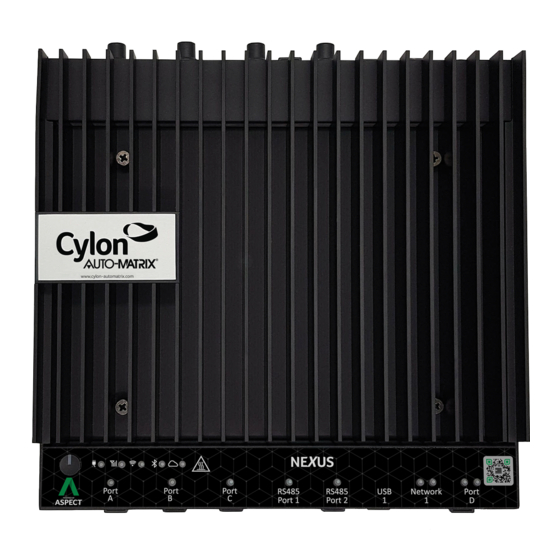
Page 9: Bottom Panel (Ports)
Enable/disable the bias resistor for RS485 port 1. RS485 port 2 resistor switch Enable/disable the differential termination resistor for RS485. RS485 port 2 bias resistor switch Enable/disable the bias resistor for RS485 port 2. MAN0125 Rev 19 © Cylon Controls... -
Page 10: Top Panel
Connect a monitor or other HDMI device. Provides video and audio output. Note: In order to function the HDMI must be connected when the system boots. USB 2.0 port Unused USB 2.0 port Unused © Cylon Controls MAN0125 Rev 19... -
Page 11: Left Edge
Site’s central server, hosting the primary UI and historical data, it is recommended that its power supply is connected to an Uninterruptible Power Supply (UPS). RIGHT EDGE IO expansion port Unused MAN0125 Rev 19 © Cylon Controls... - Page 12 This page is intentionally blank © Cylon Controls MAN0125 Rev 19...
-
Page 13: Section 2 : Installation And Configuration
SECTION 2 : INSTALLATION AND CONFIGURATION... -
Page 14: Powering On The Nexus Series Device
The NEXUS Series device is designed for specific applications and needs to be installed by qualified personnel with RF and regulatory-related knowledge. POWERING ON THE NEXUS SERIES DEVICE Install the NEXUS Series device on the wall mount using a wall... - Page 15 Each RS485 cable must be plugged into a surge protector, and the protector plugged into one of the NEXUS Series device’s RS485 ports: Additional units can be ordered if required, in packs of two. Note: Turn on the corresponding dip switches to enable the network bias and termination.
-
Page 16: Mounting The Nexus Series Device On The Wall
MOUNTING THE NEXUS SERIES DEVICE ON THE WALL You can mount the NEXUS Series device on a wall by using mounting brackets (sold separately). Secure the two mounting brackets to the back of the NEXUS Series device by using four screws. -
Page 17: Mounting The Nexus Series Device On A Din Rail
MOUNTING THE NEXUS SERIES DEVICE ON A DIN RAIL NEXUS Series device can be mounted on a DIN rail. The DIN rail bracket mounts to the back of the NEXUS Series device. Align the screw holes on the DIN rail mount to... - Page 18 This page is intentionally blank © Cylon Controls MAN0125 Rev 19...
- Page 19 SECTION 3 : DETAILED ENGINEERING SPECIFICATIONS...
-
Page 20: Dimensions And Weight
295 mm (11.63 in) Depth 156 mm (6.13 in) Shipping weight 3.8 kg (8.38 lb) (includes packaging materials) MOUNTING DIMENSIONS Height 246 mm (9.69 in) Width 228.4 mm (8.99 in) Depth 72.7 mm (2.86 in) © Cylon Controls MAN0125 Rev 19... -
Page 21: Environmental And Operating Conditions
-15.20 m 5000 m (-50 ft 16,404 ft) Note: The maximum operating temperature is derated 1°C/305 m (1000 ft) above sea level altitude. … … Storage -15.20 m 10,668 m (-50 ft 35,000 ft) MAN0125 Rev 19 © Cylon Controls... -
Page 22: Power
Never Earth or Ground any of the terminals connected to this power supply. Never use this power supply to power CB, NB, or SBC control devices, or any other equipment, because it is possible that the other equipment may be connected to Earth or Ground. © Cylon Controls MAN0125 Rev 19... -
Page 23: Communications-Ethernet
General specifications Capacity (bytes) 64 Gb Dimensions inches (W x D x H) 3.94 x 2.75 x 0.374 Interface type and maximum speed Up to 6 Gb/s (SATA 3.0) MTBF 800,000 hours Logical blocks 500,118,192 MAN0125 Rev 19 © Cylon Controls... - Page 24 This page is intentionally blank © Cylon Controls MAN0125 Rev 19...
-
Page 25: Section 4 : Software Configuration
SECTION 4 : SOFTWARE CONFIGURATION... -
Page 26: Introduction
NTRODUCTION The following provides details on the software configuration of the NEXUS Series hardware. Please follow the steps contained within this section for proper setup and configuration. TOOLS REQUIRED The following tools will be required for proper configuration of the system: •... -
Page 27: Connecting To A Nexus Series Device
CONNECTING TO A NEXUS SERIES DEVICE NEXUS Series device is shipped with a default IP address ( ) and subnet mask ( ) on 192.168.1.251 255.255.255.0 the primary Ethernet Port. Your laptop’s network card must be configured in a manner where it may access this IP network setting. -
Page 28: Log-In
To log-in to the NEXUS Series device: With your PC’s network card configured, open any standard web browser. Browse to the IP address of your NEXUS Series device as defined during installation. If your connection is successful, the main login page of... -
Page 29: Project Instances
Aspect Control Engine Logs • License Item Status • Project Thread Status CALENDAR CONFIGURATION The Calendar Configuration area is used to configure iCalendar integration variables of the NEXUS Series device. Within this section there are two pages: • Calendar File • Calendar User... -
Page 30: Calendar User
Calendar User provides the ability to change the default username and password credentials that are required to allow iCalendar-based tools to publish data to the NEXUS Series device. By default, the username (calendar) and password (user) can be changed to any desired credential set. When referencing Calendars in Aspect Studio, these credentials must be specified in order to properly access the file. -
Page 31: Instance Services
The Persistence Manager area is used to manage and delete Persisted data. Persisted data is localized data stored from Persisted Elements that may be present in an Aspect project, as well as data persisted by vSTAT elements when such functionality is implemented in a delivered solution. MAN0125 Rev 19 © Cylon Controls... -
Page 32: Project Source
The Aspect Control Engine log provides administrators and technicians the ability to view project status and debugging information relating to the health of the deployed Aspect project. Up to 10 pages of Aspect logs are contained and individual logs can be downloaded. © Cylon Controls MAN0125 Rev 19... -
Page 33: License Item Status
Ports being used by the Aspect project loaded into the target. By default, the all Tabs will update information every 15 seconds. You may adjust this update timer by choosing the Settings tab, and changing the Global Settings Update time. MAN0125 Rev 19 © Cylon Controls... -
Page 34: Database Management
• Username - matrixac1 • Password - aam Note: MySQL administration in ASPECT and later uses Adminer. However, on devices running 3.03.02 or earlier the UI for MySQL administration is based on phpMyAdmin: 3.03.01 © Cylon Controls MAN0125 Rev 19... -
Page 35: Sqlite Maintenance
NEXUS Series device as well as a method to upload/download license files. If a license file is uploaded, Cylon Controls recommends rebooting the NEXUS Series device to ensure the license file is successfully applied. -
Page 36: Communication Setup
Manual OOS check boxes. BACNET SETTINGS BACnet Configuration area allows configuration of read/write retries, port configuration, and router settings for BACnet/IP. © Cylon Controls MAN0125 Rev 19... -
Page 37: Bbmd Settings
BACnet/IP Broadcast Management Device (BBMD) table setup for BACnet networks. MODBUS NETWORK PROPERTIES Modbus Network Properties page is used to set the configuration for Modbus communications. TIME SYNC SETTINGS Time Sync Settings area provides the ability to configure BACnet network time synchronizations. MAN0125 Rev 19 © Cylon Controls... -
Page 38: System Administration
YSTEM DMINISTRATION The System Administration area contains system settings for the NEXUS Series device. These fields include the User Manager, System Services, System Status, System Updates, Ethernet Settings, Time Settings Web Server Configuration, Process Status, Image Proxy Configuration, and CalDAV Server Configuration. -
Page 39: Process Status
System Updates area is used to perform firmware upgrades to the ASPECT device. These firmware updates can be obtained from Error! Unknown document property name.. Clicking on the Continue button opens the upload page: MAN0125 Rev 19 © Cylon Controls... -
Page 40: Os Auto Update
Download button. ETHERNET SETTINGS Ethernet Settings area permits for Ethernet address configuration of the NEXUS Series device. The NEXUS Series device can support static IP addresses or DHCP addressing from a valid DHCP server. Simply select the appropriate address setting for your application. -
Page 41: Network Diagnostics
TIME SETTINGS The Time Settings area allows users to configure the NEXUS Series device Time and Date parameters. In this section, users can set the following items using the appropriate drop-downs and editors: •... -
Page 42: Web Server Configuration
Aspect Control Engine - defaults to port 7226 • Simple Mobile Web - defaults to port 8080 IMAGE PROXY CONFIGURATION The Image Proxy Configuration page permits users to enable to disable image proxy, allowing Aspect to access external sites retrieve graphics. © Cylon Controls MAN0125 Rev 19... -
Page 43: System Logs
• Diagnostic Buffer - provides kernel operating system output for the device. The information shown here is for diagnostic purposes and may be referenced during troubleshooting session with Cylon Controls. • Remote Logging - The Remote Logging page is used to allow or disallow centralized syslog messaging. All Aspect targets support the ability to send their log information to a centralized Aspect target or IT-supported syslog server. -
Page 44: System Log
The System Log area provides complete syslog information for the hardware. Information provided within this log includes boot up details and lower level information regarding runtime of the system. UPDATE LOG The update log shows all recent updates to the operating system. © Cylon Controls MAN0125 Rev 19... - Page 45 This page is intentionally blank MAN0125 Rev 19 © Cylon Controls...
- Page 46 CYLON AUTO-MATRIX | AMERICAS ONE TECHNOLOGY LANE EXPORT PA 15632, USA T + 1 724-733-2000 F +1 724-327-6124 E CONTACTUS@CYLON.COM IRELAND CYLON CONTROLS LTD. | GLOBAL HEADQUARTERS CLONSHAUGH BUSINESS & TECHNOLOGY PARK CLONSHAUGH DUBLIN 17 IRELAND T + 353 1 245 0500 F + 353 1 245 0501 E INFO@CYLON.COM...
Need help?
Do you have a question about the NEXUS Series and is the answer not in the manual?
Questions and answers