Advertisement
Quick Links
NDM
Rotary Gas Meter Installation and Operation Manual
TM
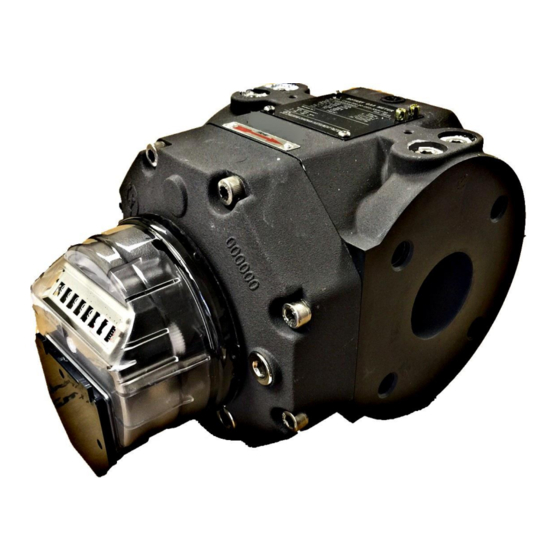
The NMT
NDM Rotary Displacement Gas Meter is a positive displacement type of meter
which,
by means of two counter-rotating impellers and a counting
mechanism,
measures a known
TM
volume of gas with each rotation. As a result of years of development and
experience,
NMT
has been able to provide a meter of unparalleled accuracy and turn down ratio. The construction
of the meter and the materials used will give years of faithful service even under very demanding
conditions. The special designed coupling guarantees flexibility in functionality for the
future,
since indexes and electronic switches can be replaced on-site with the meter in-line.
The purpose of this manual is to provide a general guide to the
installation,
operation and care
TM
of a standard NMT
NDM Rotary Displacement Gas Meter. Every effort has been made to ensure
that the information contained in this manual is as accurate as possible;
however,
the continuous
TM
improvements which NMT
makes to its products may result in small inconsistencies. It is
therefore prudent to consult the specific technical data sheets and other documents which
TM
accompany the meter. If in any
doubt,
NMT
should be consulted.
Page 1 of 13
Advertisement

Subscribe to Our Youtube Channel
Summary of Contents for NMT NDM
- Page 1 Rotary Gas Meter Installation and Operation Manual The NMT NDM Rotary Displacement Gas Meter is a positive displacement type of meter which, by means of two counter-rotating impellers and a counting mechanism, measures a known volume of gas with each rotation. As a result of years of development and experience, has been able to provide a meter of unparalleled accuracy and turn down ratio.
-
Page 2: Table Of Contents
Rotary Gas Meter Installation and Operation Manual CONTENTS 1. GENERAL DESCRIPTION RECEIVING, HANDLING AND STORAGE 3. INSTALLATION 4. MAINTENANCE 5. TROUBLE SHOOTING 6. TECHNICAL DATA APPENDIX A. Installation Flow Orientation B. Oil Fill location C. Pulse Output Info Page 2 of 13... -
Page 3: General Description
The flowing gas volume is proportional with the number of revolutions of the output. The output of the NDM Rotary Gas Meter is a special designed magnetic coupling where one part is fitted inside the meter body and the associated part is in the read-out unit. -
Page 4: Receiving, Handling And Storage
NDM. When connecting these accessories, reference should be made to the instructions and other documents accompanying these products. RECEIVING, HANDLING AND STORAGE NDM Rotary Meters are precision measurement instruments. Although of very rugged construction, reasonable care should be given during handling and storage. -
Page 5: Installation
Distributor or Representative from whom the product was purchased. METER INSTALLATION Reference Appendix A: The NDM rotary meters may be installed in either a Top/Bottom Inlet (vertical) or a Side Inlet (horizontal) configuration. The preferred or recommended installation is top inlet in a vertical pipe line with gas flow downward. - Page 6 5) Connect connectors to the index according to the diaphragms accompanying the meter. 6) There is only one oil reservoirs in the NDM meter. Oil is shipped with each new meter in a quantity sufficient to fill the reservoir in either a Top Inlet or a Side Inlet configuration. See Appendix B.
-
Page 7: Maintenance
. Oil change frequency will depend upon the cleanliness of the gas being measured. Change oil when the level increases significantly, indicating an accumulation of moisture. The NDM series of rotary meters require an oil change once every 5 to 10 years under favorable operating conditions. -
Page 8: Trouble Shooting
Damage to the bearings, impeller or gears usually results in excessive noise and/or vibration. If it is suspected that the problem is confined to the index, the index can be replaced while the line remains pressurized. Contact NMT or the NMT representative for the exchange procedures. -
Page 9: Technical Data
Rotary Gas Meter Installation and Operation Manual TECHNICAL DATA NDM 15C thru 5M NDM 7M thru 38m Bolt WEIGHT SIZE A (in) B (in) C (in) D (in) E (in) F (in) H (in) (lb) 2.13 4.76 6.73 1.5”NPT 4.96 3.35... - Page 10 Rotary Gas Meter Installation and Operation Manual SPECIFICATION UNITS 1500 Base Qmax ACFH 3000 5000 7000 11000 16000 23000 38000 Max. Operating Pressure PSIG Temp Range -22F to 140F 80:1 Turndown Ratio 160:1 Over Range Capability 2.12 Start Rate 1.7655 2.4717 3.531 5.2965...
-
Page 11: Appendix
Rotary Gas Meter Installation and Operation Manual APPENDIX Pr T A) FLOW ORIENTATION Temp Tap/Probe Pr/P = Pressure Tap/Probe Arrow=Flow Direction T Pr Page 11 of 13... -
Page 12: Oil Fill Location
Rotary Gas Meter Installation and Operation Manual APPENDIX B) Oil Fill Locations Meter Oil Capacity(ml) Vertical 310*2 310*2 310*2 Horizontal Page 12 of 13... - Page 13 Rotary Gas Meter Installation and Operation Manual APPENDIX C) Pulse Output Page 13 of 13...
Need help?
Do you have a question about the NDM and is the answer not in the manual?
Questions and answers