Table of Contents
Advertisement
Quick Links
Advertisement
Table of Contents

Summary of Contents for iO MatchBox Series
- Page 1 Continuous Wave laser Version 2.5 October. 2020...
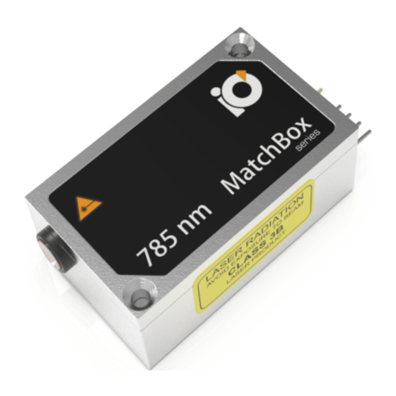
- Page 3 MatchBox® series | User Manual INTRODUCTION As the title hints, MatchBox® products are ultra-compact, single-unit laser sources with overall dimensions comparable to a regular matchbox (30x50x18 mm ), connector pins not included. The MatchBox® series include a range of continuous wave laser sources, featuring wide range of wavelength, output power, output type and line- width options.
- Page 4 Integrated Optics...
-
Page 5: Table Of Contents
MatchBox® series | User Manual CONTENTS SAFETY INFORMATION ..........5 Labels ................. 5 Electrical safety ............6 Optical Safety ............. 6 Laser Safety and Classification ........9 DESCRIPTION AND SPECIFICATIONS ......11 Part Numbers ............. 11 Description of Series .......... - Page 6 Integrated Optics Laser Control Software ..........33 Changing Output Power..........46 Communication Command Table ....... 46 Communication with Multiple Lasers in a Bus .... 50 TTL Modulation ............52 Attaching Control Interfaces........54 ACCESSORIES..............55 TROUBLESHOOTING Q&A ...........
-
Page 7: Safety Information
MatchBox® series | User Manual SAFETY INFORMATION 1.1: Labels Along the text you will find icons designed to draw your attention to different bits of safety or otherwise important information: This icon is used to draw your attention to important information, related to the usage of a laser. -
Page 8: Electrical Safety
Integrated Optics Figure 1-2. Serial number is marked on the back of the laser body, right above the pin connection. 1.2: Electrical safety Do not disassemble the enclosure. All units are designed to be operated as assembled. Warranty will be voided if the enclosure is opened. Electric shocks from an unsuitable or poorly grounded power supply, can cause extreme pain, severe burns, cardiac arrest and in some cases can be even lethal, that is why the operator should always obey the safety... - Page 9 MatchBox® series | User Manual emitting diodes and etc. It is important for users or other persons approaching to laser systems, to know the dangers involved. Only users, who are familiar with laser safety should use laser systems, this way the risks of laser radiation related accidents would be minimized.
- Page 10 Integrated Optics photomultipliers. It is important to make sure that an unattenuated beam does not strike any of aforementioned devices directly. Calculation of allowed fluency is necessary before using such devices with our lasers. In addition to laser safety from the laser source alone, given safety precautions must be followed: •...
-
Page 11: Laser Safety And Classification
The laser meets the emission requirements for Class 3B or Class 4 as specified in EN55011:2009. Compliance of lasers within the MatchBox series with the (EMC) requirements is certified by the CE mark. MatchBox lasers are OEM dedicated lasers and usually come without necessary safety means. - Page 12 Integrated Optics...
-
Page 13: Description And Specifications
DESCRIPTION AND SPECIFICATIONS 2.1: Part Numbers The part number is composed for the MatchBox series CW lasers as follows: Figure 2-1. Understanding part numbers of the MatchBox CW lasers. The part number of MatchBox lasers is composed of five sections: •... -
Page 14: Description Of Series
2.3: Thermal Management The MatchBox series includes DPSS (Diode pump solid state) and direct diode lasers. Depending on model, one or two thermo-electric coolers (TEC) are equipped inside the enclosure for thermal management of a pump laser diode and associated optics. -
Page 15: Power Supply
2.4: Power Supply The MatchBox series include a variety of lasers featuring different power ratings, thus requiring different power supply parameters. Power supply requirements are provided below. - Page 16 0.4-0.5 A Diode XXXXL- Voltage of 5 V is needed to be supplied for this type of MatchBox series lasers. Lasers of the same model could require different current. For instance, low-power laser 405L-21A needs maximum current of 0.6 Amps and typical of 0.3 Amps, whereas it is estimated that low-power laser...
- Page 17 MatchBox® series | User Manual For direct diode lasers the optimal power supply that is 18W PD type USB power supply (AM-P7), while for DPSS lasers it is recommended to use 25 W, but optimally 45W to 60W PD type (depending on other accessories used) power supply (AM-P8).
-
Page 18: Cables
Integrated Optics 2.5: Cables The MatchBox laser features an OEM design, where integrators implement their own physical interface to connect directly to the pins of the laser. This is the reason why it is sold without any cables in its standard configuration. -
Page 19: Specifications
2.7: Specifications The MatchBox series includes a variety of lasers featuring different wavelength and power ratings. The actual specifications of a laser are provided in a test report accompanying a laser, which is sold to the customer. - Page 20 Integrated Optics permanently fixed fibers, have different arrangements on the front facet of the laser. Figure 2-3. Top and side view drawing of the MatchBox free-space laser.
-
Page 21: Laser Output Options
MatchBox® series | User Manual Figure 2-4. Top and side view drawing of the fiber coupled MatchBox laser. 2.9: Laser Output Options MatchBox laser sources are offered in two main configurations regarding to the type of the output. - Page 22 Integrated Optics Free-space output is commonly used in compact (portable) laser setups, where working area (an object to be irradiated) is relatively close to the laser source and the beam could be delivered directly or using just a few mirrors. Furthermore, the free-space output versions are provided with a PTFE safety cap (not shown in pictures), which might be necessary for a scientific open-frame setup.
- Page 23 MatchBox® series | User Manual single-mode polarization maintaining (blue) fiber, could be arranged with this output type. Fiber with metal protection bend radius is 30 mm and fiber without metal protection bend radius is 20mm. Lasers with non-detachable fibers feature lower output power, 2-3 times worse output power stability, but significantly improved beam shape and homogeneity, as compared to free-space versions.
-
Page 24: Operating Environment
Integrated Optics of time, in case minor adjustments need to be made without stopping the laser, thus stable operation is not lost. This output option is designed for custom multi-mode fiber installations. Fiber can be supplied optionally upon clients request. Figure 2-7. -
Page 25: Installation
MatchBox® series | User Manual INSTALLATION 3.1: Preliminary Checks Every MatchBox unit is packed in an antistatic foam package, which is arranged to protect electronics inside the laser from charge accumulation. The same foam is also used for absorbing mechanical shocks well during transportation. -
Page 26: Heatsink Requirements
Integrated Optics After unpacking, save the laser package boxes for potential later shipments. Table 3-1. Contents of a typical package. Item Quantity Laser Source 1 unit Thermal Paste (1 1 unit gram) Countersunk 2 units Screws M2.5x25 mm If there is an extra screw, it is used for mounting the Break-out-Box to a heatsink or an adapter. - Page 27 MatchBox® series | User Manual Integrated Optics, UAB recommends to use a thermal paste between a MatchBox continuous-wave laser and a heatsink to provide proper thermal contact. The mounting surface of a heat sink should be flat within <0.05 mm over the mounting surface.
-
Page 28: Heatsink Installation
Integrated Optics 3.3: Heatsink Installation The CW MatchBox configurations include DPSS and direct diode lasers, whereas the higher power DPSS lasers tend to generate more excessive heat than diode lasers. Furthermore, all MatchBox lasers are equipped with an internal TEC (Peltier) thermal management element, which, when operated, generates even more heat to stabilize the optical components inside the laser, thus it is required to attach the laser enclosure to an external heatsink. -
Page 29: Starting The Laser
MatchBox® series | User Manual 3.4: Starting the laser Starting a MatchBox CW laser is quite simple: 1. The laser has to be mounted and secured on a heatsink; 2. A Break-out-Box or any other UART has to be connected to the laser pins. - Page 30 Integrated Optics After the .zip file is extracted, the CP210xUSB to UART Bridge Driv- er has to be installed. Depending on the operational system of a comput- er, click on either CP210xVCPInstaller_x64 or CP210xVCPInstaller_x86. Figure 3-2. Initial installation window. While installing the driver a user will be asked to read and accept the license agreement to proceed.
- Page 31 MatchBox® series | User Manual After the agreement is accepted, the driver will automatically install and a user is informed about the successful installation. Figure 3-4. Installation complete window. When drivers are installed successfully, the MatchBox-Controller file can be opened. It is a portable application and it does not need to be in- stalled.
- Page 32 Integrated Optics...
-
Page 33: Operation
MatchBox® series | User Manual OPERATION 4.1: Operating Fiber Coupled Laser Fiber coupled diode or DPSS laser is a compact and robust unit for alignment-free operation throughout the lifetime of the laser. Proprietary fiber coupling technology ensures good power stability and excellent fiber-coupling efficiency. -
Page 34: Operating Free-Space Output Laser
Integrated Optics The fiber cap has to be removed before turning the laser on. Starting the laser with a safety-cap attached might damage the laser and render the warranty void. Fiber coupled lasers must be turned on via MatchBox laser control software. -
Page 35: Uart Bus
MatchBox® series | User Manual Figure 4-2. Exemplary Free-space Output of MatchBox laser. 4.3: UART bus UART (Universal Asynchronous Receiver/Transmitter) is a commonly used communication device in computer based systems. Integrated Optics, UAB offers a few UART communication options: it can be converted to USB and RS232 by using a Break-out-Box with USB control interface (AM-C8) or RS232 control interface (AM-C3). - Page 36 Integrated Optics advised to check in ‘Device manager’ (in Windows operating system) if a COM port is created. Once the COM port is created open Integrated Optics, UAB laser control software and choose a required serial port. If no ports appear, refresh the software window by clicking the ‘refresh’ button at the bottom of the page.
- Page 37 MatchBox® series | User Manual Figure 4-4. The main software window for CW lasers. The software window is shown in Figure 4-4. The window is divided in four segments. Each segment represents different control fields of the MatchBox laser: Right above the first segment a port number, an item name, a serial number and a hardware version can be seen.
- Page 38 Integrated Optics if laser is in ACC mode, it means that laser is in automatic current control mode. It keeps the laser diode current constant and output power can only be changed by changing mA value; if laser is in APC mode, it means that laser is operating in automatic power control mode.
- Page 39 MatchBox® series | User Manual laser parameters make the laser operate undesirably, the user can always simply disconnect the laser from USB and power supply and connect it again - the old settings will be restored and displayed on the screen.
- Page 40 Integrated Optics Next, we will briefly describe particular lines of the software window. These lines are accessed through ‘more...’ section in the top right corner of the main software window. Figure 4-6. ‘more...’ section view ‘more...’ section provides detailed information about a laser: item code, serial number, firmware version, operational time (laser working time), started time (how many times turned on), and virtual port.
- Page 41 MatchBox® series | User Manual Figure 4-7. ‘Send Command’ section view ‘Send command’ section is used for sending commands directly to the laser. See which commands can be sent in paragraph “Communication Command Table” on page 46 Entering commands with higher access levels might cause undesirable laser function.
- Page 42 Integrated Optics Figure 4-8. ‘Access level’ section view. If laser is operated without control software, access level can be changed to Level 1 with a command ‘c u 1 1234’. For access level 2 and level 3 code please contact your distributor or Integrated Optics, UAB technical support.
- Page 43 MatchBox® series | User Manual Figure 4-9. ‘Programmable pin’ section view ‘Programmable pin’ section is used to define programmable pin configuration. To program this pin access level 2 or 3 is required. ‘P0’ setting is for direct diode laser TTL modulation (electronics version 1.3v);...
- Page 44 Integrated Optics ‘P4’ is for DPSS type continuous wave laser TTL modulation (electronics version 11.4.XX). Modulation speed is up to 500 Hz. Figure 4-10. ‘Fan Temperature’ section view ‘Fan temperature control’ section is used for controlling fan rotation speed. Fan speed can be set to maintain the laser body temperature in the range from 15 deg.C to max 35 degrees.
- Page 45 MatchBox® series | User Manual Figure 4-11. ‘Generate Report’ section view. ‘Generate report’ section provides user the ability to generate a report about the laser. This report generates information about what settings were set, what are laser readings, like, temperature, diode current and other parameters.
- Page 46 Integrated Optics Figure 4-12. ‘Graph’ section view. ‘Graph’ section is a very handy tool to check how laser behaves in longer periods of time. It can be used to identify many issues regarding laser operation instabilities. This section can track: 1) diode temperature;...
- Page 47 MatchBox® series | User Manual It is recommended, if possible, to generate this graph for 30 minutes before contacting Integrated Optics, UAB technical support about laser operation issues. More than one laser can be connected to a computer simultaneously. All connected lasers can be controlled with multiple program windows –...
-
Page 48: Changing Output Power
4.6: Communication Command Table The following commands are used with MatchBox series lasers at serial communication rate of 115200 bps. The ‘˽’ sign means space. Table 4-1. Communication commands of MatchBox lasers. Access... - Page 49 MatchBox® series | User Manual Table 4-1. Communication commands of MatchBox lasers. Access Comm Argument Function Returned Value Example Level c˽1˽ set crystal temperature 2550 <ACK> or <ERR> to 25.5 °C c˽2˽ set laser diode 2550 <ACK> or <ERR> temperature to 25.5 °C c˽3˽...
- Page 50 Integrated Optics Table 4-1. Communication commands of MatchBox lasers. Access Comm Argument Function Returned Value Example Level r˽s receive settings. #Settings: 1800 Returned values are: 2350 90 850 nan crystal set temp, laser 170 Autostart: OFF diode set temperature, 3 3200 laser diode set current, feedback value, optical power set...
- Page 51 MatchBox® series | User Manual Table 4-1. Communication commands of MatchBox lasers. Access Comm Argument Function Returned Value Example Level r˽i Receive laser Firmware information. Returned MatchBox2 values are: firmware v1.7.648 version, serial number, Laser S/N: 915322 product code, operating Laser model: 405L- time, the number of times the laser diode...
-
Page 52: Communication With Multiple Lasers In A Bus
Integrated Optics • 3 - laser busy, task is not complete please wait for 1 s and try again • 4 - arguments out of range • 5 - unknown command • 6 - laser must be enabled to execute this command 4.7: Communication with Multiple Lasers in a Bus There are several ways, how integrators can connect and control multiple... - Page 53 MatchBox® series | User Manual One example of such communication is shown in Figure 4-14, where the system UART enquires all lasers in the bus to send their IDs. All lasers respond randomly. Figure 4-14. ID request sent from the system UART to a bus with multiple lasers.
-
Page 54: Ttl Modulation
Integrated Optics Controlling multiple lasers in one window with Integrated Optics, UAB software isn’t possible. It is only an example for integrators. 4.8: TTL Modulation TTL stands for transistor-transistor-logic. In the context of laser modules, TTL modulation means a convenient and standardized method for lasers’ modulation. - Page 55 MatchBox® series | User Manual To find out how laser operation is affected by different TTL modulation pin states, check the table below. Table 4-2. Laser control via TTL input truth table TTL input Laser output Open Low (0 V) High (+ 3.3 VDC and above) Note: In all cases laser is either ON, using GUI or is autostart enabled.
-
Page 56: Attaching Control Interfaces
Attaching Control Interfaces The pins of the laser can be attached to control interfaces, which are designed as accessories of the MatchBox series. On the other hand, in OEM arrangements, the pins can be connected to a custom electronics within an instrument or portable laser equipment, which is arranged to work as a control interface for the laser. -
Page 57: Accessories
MatchBox® series | User Manual ACCESSORIES Integrated Optics, UAB offers a variety of accessories for heat management, power supplying and mounting. As our company strives for perfection and diversity, our engineers and researchers work hard everyday to make improvements of our products, especial in new products newly created equipment. - Page 58 Integrated Optics...
-
Page 59: Troubleshooting Q&A
MatchBox® series | User Manual TROUBLESHOOTING Q&A Whether there are any technical issues concerning our products or any general questions, we are always willing to answer it as fast as possible via email or phone. In order to save both our and our clients time, we have provided a list of frequently asked questions. - Page 60 TEC load should not exceed 80%, with rare exceptions. Q: What accessories are needed in order to use MatchBox laser? A: The MatchBox series is designed for OEM applications. Integrators can install the laser without any other accessories, just by providing 5 V at 1.5-2 A and UART control signals to the Vcc and GND pins on the back...
- Page 61 MatchBox® series | User Manual USB converter chip (SiLabs) and a micro USB socket for data communication. Also, it converts PD type (Power Delivery) power supply input to a suitable and stable voltage and current output for a laser. Q: I changed the laser power in the control software, but after restart of the system the new power setting was not saved? A: New parameters are not saved in the micro-controller of the laser unless ‘Save settings’...
- Page 62 Integrated Optics Warranty becomes obsolete in cases indicated in “WARRANTY” on page 67. Q: I have ordered an SLM laser, but can observe more than one longitudinal mode. How can I solve this problem? A: It is possible that laser is working at non-optimal temperature point. First step is to make sure that the laser gets enough heat dissipation.
- Page 63 MatchBox® series | User Manual Q: Is there a recommended way to improve the diode laser’s longevity? A: Cold start is one of the factors reducing the lifetime of laser diodes, especially pump laser diodes in DPSS lasers. ‘Warm-up’ is the best mode for stand-by operation to improve the longevity of the laser diode or the pump diode.
- Page 64 Integrated Optics particular situations after consulting with the support team at Integrated Optics, UAB. Q: After a while, laser power dropped by a few mW, why is that? A: There could be a few reasons why the laser power might drop by few 1.
-
Page 65: Glossary
MatchBox® series | User Manual GLOSSARY °C Degrees Celsius µm Micrometer = 10 A/Amps Amperes Alternating Current Automatic Current Control Automatic power control Break-out-Box Bytes Per Second Charge-coupled device CDRH Centre for Devices and Radiological Health Centimetre Continuous Wave Digital-to-Analog Converter Direct Current DPSS Diode-Pumped Solid-State... - Page 66 Integrated Optics Kilohertz = 10 Laser Diode Megahertz = 10 Multi-Mode mrad Milli-radian = 10 radians Milliwatt = 10 Watts Nanometre = 10 meter N·m Newton metre Negative Temperature Coefficient Original Equipment Manufacturer Printed Circuit Board Polarization maintaining Polyvinyl Chloride Pulse Width Modulation Root Mean Square...
- Page 67 MatchBox® series | User Manual RoHS Restriction of Hazardous Substances RS232 Standard serial communication transmission of data Receive Single-Longitudinal-Mode Thermo-Electric Cooler Transistor-Transistor Logic Transmit UART Universal Asynchronous Receiver/Transmitter Universal Serial Bus Voltage at the Common Collector Volume Bragg Grating...
- Page 68 Integrated Optics...
-
Page 69: Warranty
MatchBox® series | User Manual WARRANTY Integrated Optics, UAB warrants the MatchBox laser to the original purchaser (the Buyer) only, that the laser system, that is the subject of this sale, (a) conforms to specifications provided before a certain laser has been shipped to the buyer and (b) is free from defects in materials and workmanship. -
Page 70: Limitations Of Warranty
Integrated Optics 8.1: Limitations of Warranty The foregoing warranty shall not apply to defects resulting from: • Components and accessories manufactured by companies, other than Integrated Optics, UAB, which have separate warranties, • Improper or inadequate maintenance by the buyer, •... - Page 71 MatchBox series | User Manual ®...
- Page 72 Integrated Optics...
Need help?
Do you have a question about the MatchBox Series and is the answer not in the manual?
Questions and answers