Table of Contents
Advertisement
Quick Links
Advertisement
Table of Contents

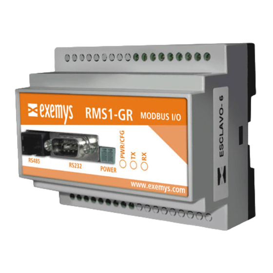
Summary of Contents for exemys RMS1-GR
- Page 2 RMS1 – GR User’s Manual Exemys The Exemys products are in permanent evolution to satisfy the needs of our clients. For this reason, specifications and capabilities are subject to change without previous notice. Please find updated information at www.exemys.com Copyright © Exemys, 2008. All Rights Reserved.
-
Page 3: Table Of Contents
RMS1 – GR User’s Manual Exemys Contents Introduction Purpose of this manual.................... 4 Conventions, terms and abbreviations ..............4 General Description of the Product ................. 4 Power Supply ......................6 Serial Port Connection .................... 7 1.5.1 RS-232 Connection ....................7 1.5.2... -
Page 4: Introduction
Ground (Reference to tension) General Description of the Product The RMS1-GR is a device for the acquisition and control of digital and analog inputs and outputs, by means of the Modbus Slave Serial ASCII/RTU. The equipment has up to 16 opto-isolated or transistor inputs, up to 16 transistor or relay outputs and up to 6 analog inputs (0-10V / 4-20mA), all according to the different models of equipment. - Page 5 RMS1 – GR User’s Manual Exemys www.exemys.com...
-
Page 6: Power Supply
RMS1 – GR User’s Manual Exemys Power Supply Figure 1 - Power Supply Terminals www.exemys.com... -
Page 7: Serial Port Connection
RMS1 – GR User’s Manual Exemys Serial Port Connection The RMS1-GR has an RS232 serial port in a DB9 connector or an RS485 serial port in a RJ45 connector. Important Note: Only one port at a time can be used and not simultaneously. -
Page 8: Led Indicators
RMS1 – GR User’s Manual Exemys LED Indicators RMS1-GR device has 3 LED Indicators: Power, Rx and Tx. Power LED This LED indicates different device statuses. When energizing the equipment, the Power LED flickers rapidly during the first 7 seconds, indicating the time to enter the “CFG”... - Page 9 Exemys Power LED Rx LED Tx LED Description Very fast RMS1-GR is starting. 7 seconds are given to enter the configuration mode through the CFG command blink via console. RMS1-GR has entered the configuration mode of the Slow blink equipment.
-
Page 10: Models
RMS1 – GR User’s Manual Exemys Models Models The RMS1-GR family of products has different types of digital and analog inputs and outputs. Up to 16 Digital Inputs, Opto-isolated or transistor • Up to 16 Digital Outputs, Transistor or with relays •... -
Page 11: Serial Configuration
Serial Configuration General Description The RMS1-GR equipment features a configuration mode through a very intuitive Serial console that allows quick and simple configuration of the equipment. You gain access to the configuration menu within 7 seconds after powering up the equipment. - Page 12 RMS1 – GR User’s Manual Exemys 1) RTU 2) ASCII ESC returns to the previous menu Selecting option (2) in the main menu you can gain access to the configuration of the serial port parameters, either, Baud Rate, Data Bits or Parity Bits.
- Page 13 RMS1 – GR User’s Manual Exemys In the “Show Configuration” submenu Current configuration -------------------- Modbus: ASCII Serial: Baud Rate: 9600 Data Bits: 8 Bits Parity: No Parity Slave: Exceptions: Activated Selecting option (7) of the main menu you exit saving the last updated configuration.
-
Page 14: Modbus Map
REGISTER 40012 The RMS1-GR has 16 digital inputs, 16 digital outputs and 6 analog inputs. It should be noted that address 30009 of the INPUT REGISTER, which contains the digital input statuses of the equipment, bit 0 (or the least significant) corresponds to digital input 1, and bit 15 (the most significant) corresponds with digital input 16. - Page 15 RMS1 – GR User’s Manual Exemys The HOLDING REGISTER 40001 to 40010 and 40012 are used for general purpose only. This means that you can save data for later use. The register 40011 is used to write all the Digital Outputs at the same time.
-
Page 16: Modbus Master
Exemys Modbus master (I/O Tunnel) The Modbus master mode allows you to create a digital I/O tunnel using two RMS1-GR devices. Module digital inputs will be replicated on the other’s outputs and vice versa. These are the requisites to make this configuration work. - Page 17 RMS1 – GR User’s Manual Exemys RS485 www.exemys.com...
-
Page 18: Pin Out
Digital Input (opto-isolator /Transistor). X: Input number OUTx Digital Outputs (Relay/Transistor). X: Output number Ground Opto-isolator or relay common terminal Inputs/outputs groups RMS1-GR’s input and output terminals are divided into groups depending on IO type. Pin out of existing models www.exemys.com... - Page 19 RMS1 – GR User’s Manual Exemys RMS1-TT-110-1616-0X-GR-MB RMS1-TT-110-168-6V-GR-MB www.exemys.com...
- Page 20 RMS1 – GR User’s Manual Exemys RMS1-OR-110-168-6V-GR-MB RMS1-OR-110-1616-0X-GR-MB *NOTE: The terminals that are not showed in the graphics are not used in that particular model. www.exemys.com...
-
Page 21: A Technical Specifications
Input impedance Two examples of how to connect directly from the same power source of the RMS1-GR as well as an external power supply where it can be seen that they must share a common terminal are shown. www.exemys.com... -
Page 22: Digital Outputs
The digital outputs are of the open collector type. The load to be connected must be supplied with an external power supply and they must share the same GND terminal with the RMS1-GR power supply. If necessary, the same power supply to power the equipment can be used. The output is of the NPM sourcing type. -
Page 23: Digital Output To Drive A Relay
Output with relay (double power supply) 5. The relay outputs The relay outputs of the RMS1-GR allow us to open or close a circuit using the normal open and common contacts of a relay. The RMS1-GR has the particularity in relay outputs and has a common contact to each group of eight normally open contacts. -
Page 24: Analog Inputs
RMS1 – GR User’s Manual Exemys 6. Analog inputs The analog inputs are referred to the GND terminal of the RMS1-GR, so that the power supply to feed the sensor must share the GND terminal with the RMS1-GR. 6.1 Analog input voltage (0-10V) - Page 25 RMS1 – GR User’s Manual Exemys RS485 Port Connection www.exemys.com...
Need help?
Do you have a question about the RMS1-GR and is the answer not in the manual?
Questions and answers