Table of Contents
Advertisement
Quick Links
HRV / ERV INSTALLATION AND
OPERATION INSTRUCTIONS
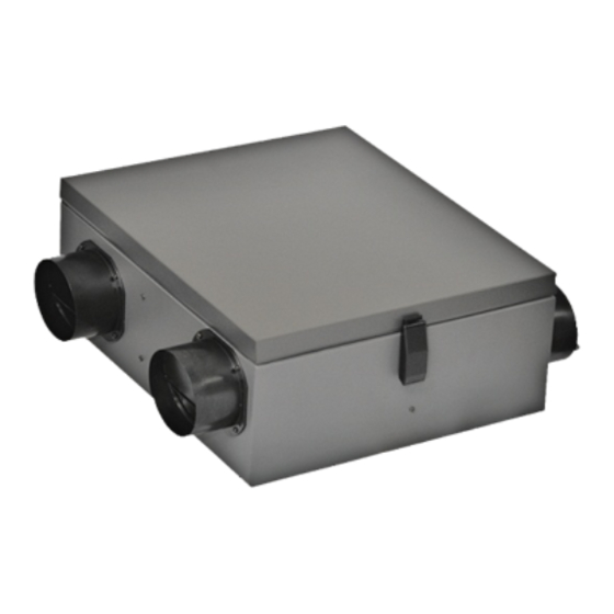
RHRV-120P ES
Polypropylene Core
RHRV-130P ES
Polypropylene Core
4 Pine Street, Toronto, ON Canada M9N 2Y8 Tel: 416-247-0045 Fax: 416-247-2012
www.ontarioheatingltd.com
Field Balancing Ports
info@ontarioheatingltd.com
New
RHRV-C100P NF
Polypropylene Core
RERV-C100 NF
Enthalpy Core
Mini Series
Model:
RHRV-80 P
Polypropylene Core
RERV-80
Enthalpy Core
Compact Series
Model:
RHRV-C100A
Aluminum Core
RHRV-C100P
Polypropylene Core
RERV-C100
Enthalpy Core
Maxum Series
Model:
RHRV-S200A
Aluminum Core
RHRV-S200P
Polypropylene Core
RERV-S200 ES
Enthalpy Core
®
2100
CERTIFIED
C
®
US
Advertisement
Table of Contents

Summary of Contents for Air Specialties Express Softaire Mini Series
- Page 1 HRV / ERV INSTALLATION AND OPERATION INSTRUCTIONS RHRV-C100P NF Polypropylene Core RERV-C100 NF Enthalpy Core Mini Series Model: RHRV-80 P Polypropylene Core RERV-80 Enthalpy Core Compact Series Model: RHRV-C100A Aluminum Core RHRV-C100P Polypropylene Core RERV-C100 Enthalpy Core Maxum Series Field Balancing Ports Model: RHRV-120P ES RHRV-S200A...
-
Page 2: Table Of Contents
IMPORTANT SAFETY INSTRUCTIONS READ AND SAVE THESE INSTRUCTIONS WARNING PACKAGING INSPECTION Open the box and check to make sure all the parts and TO REDUCE THE RISK OF FIRE, ELECTRIC SHOCK OR INJURY, OBSERVE THE FOLLOWING: accessories are present and in good condition. If you find any parts missing or any shipping damage please contact 1. -
Page 3: Rhrv-80P Rerv-80
Parts List Mini Series Model: RHRV-80P Polypropylene Core RERV-80 Enthalpy Core Optional Parts: P/N# 6PIN 6-Pin harness (Provided with new version to wire timers/ Intermittent switch & Interlock with Old version New version Furnace, Fan coil & Heat pump) RERV-80 RHRV-80P HRV / ERV - lid, Pan Assembly 9315M... -
Page 4: Rhrv-C100P, Rhrv-C100A, Rerv-C100
Parts List Compact Series Model: RHRV-C100A Aluminum Core RHRV-C100P Polypropylene Core Filter RERV-C100 Enthalpy Core Optional Parts: P/N# 6PIN 6-Pin harness (Provided with new version to wire timers/ Intermittent switch & Interlock with Furnace, Fan coil & Heat pump) Old version New version RHRV-C100A RHRV-C100P RERV-C100 9315... -
Page 5: Rhrv-C100P Nf Rerv-C100 Nf
Parts List RHRV-C100P NF 6-Pin harness (Provided with new version Polypropylene Core to wire timers/ Intermittent switch & Interlock with RERV-C100 NF Furnace, Fan coil & Enthalpy Core Heat pump) P/N# 6PIN Optional Parts: Old version New version RHRV-C100P NF RERV-C100 NF 9315 HRV / ERV - lid, Pan Assembly Polypropylene collar 5"... -
Page 6: Rhrv-120P Es, Rhrv-130P Es
Parts List Model: RHRV-120P ES Polypropylene Core RHRV-130P ES Enthalpy Core Optional Parts: P/N# 6PIN 6-Pin harness (Provided with new version to wire timers/ Intermittent switch & Interlock with Furnace, Fan coil & Heat pump) Old version New version RHRV-120PES RHRV-130PES HRV / ERV - lid, PanAssembly 9315ES... - Page 7 Parts List Maxum Series model: RHRV-S200A Aluminum Core RHRV-S200P Polypropylene Core Filter RERV-S200ES Enthalpy Core Optional Parts: P/N# 6PIN 6-Pin harness (Provided with new version to wire timers/ Intermittent switch & Interlock with Furnace, Fan coil & New version Old version Heat pump) RHRV-S200A RHRV-S200P RERV-S200ES...
-
Page 8: Wiring Diagram
Wiring Diagram Recently we modified our control board layout to provide easy wiring connections for timer switches/ Intermittent switch (low voltage) without accessing to our electrical box. Initially, some units may come with older version or newer version of Control Boards. But overall functionality of both type of boards are same. Old Version CONTROL BOARD: TC100-120... - Page 9 Wiring Diagram Recently we modified our control board layout to provide easy wiring connections for timer switches/ Intermittent switch (low voltage) without accessing to our electrical box. Initially, some units may come with older version or newer version of Control Boards. But overall functionality of both type of boards are same. New Version CONTROL BOARD: TC100-120...
-
Page 10: Furnace / Fan-Coil / Heat Pump Interlock
Wiring Diagram (cont’d) Furnace / Fan-Coil / Heat Pump Interlock: W A R N I N G Never connect a 120 volt AC circuit to the terminals of the furnace /fan-coil/heat pump interlock (Standard Wiring). Only use the low voltage class 2 circuit. Standard Interlock Wiring LO/HI Remote... -
Page 11: Hrv And Erv Typical Installations
HRV and ERV Typical Installations Typical Installations for House Fully Ducted System This is a stand alone HRV/ERV system which is not connected to a force air system. Stale air is drawn from key areas of the home (bathroom, kitchen) while fresh air is supplied to main living areas. -
Page 12: Horizontal
HRV and ERV Typical Installations (cont’d) HORIZONTAL • 32” clearance is recommended for cleaning of the core/servicing the unit. (use appropriate access door size) • Dampers are installed for horizontal installation. For vertical installation both dampers have to be turned so they can open properly and close when there is any backdraft. •... -
Page 13: Singlevent & Access Door
HRV and ERV Typical Installations (cont’d) Typical Installations of Single Vents & Access door CAULKING GRILLE Metal Clamp - 3 SIDES ONLY, NOT ON BOTTOM Insulation Intake Exhaust Duct Insulation Wallbox CAULKING WALLBOX - CAULK WALLBOX TO STRUCTURE ON ALL 4 SIDES Grille Backdraft Minimum 5 Feet... -
Page 14: Air Flow Balancing
Air Flow Balancing Balancing Procedure It is required to have balanced air flows in an HRV/ERV. The volume of air brought in from the outside must equal the volume of air exhausted by the unit while running at normal speed. If the air flows are not properly balanced, then: •... - Page 15 Air Flow Balancing (cont’d) P" DUCT DIAM CROSS SECTION AREA Note:(Option #2) Ø5” Ø6” *For balancing, extension box cover plate is 5" 0.136 sq. ft. 0.010 0.004 provided with 3 holes on supply side and 3 6" 0.196 sq. ft. 0.012 0.006 holes on exhaust side.
- Page 16 Field Airflow Balancing for House (Cont’d) Model: RHRV-80P (MINI) Model: RERV-80 (Mini) Pressure Pressure Differen al Differen al Supply Air Exhaust Air Supply Air Exhaust Air Across the Core Across the Core In. W.C. In. W.C. 0.03 0.06 0.06 0.09 0.09 0.12 0.12...
-
Page 17: Maintenance
Maintenance Regular Maintenance 1. Turn the unit off and disconnect the power supply. 2. Unlatch the door and lift the door panel towards you, hold itfirmly and slide it to the left. 3. Clean the inside of the door drain pan with a damp cloth to remove dirt and debris that may be present. -
Page 18: Troubleshooting
Troubleshooting Troubleshooting PROBLEMS POSSIBLE CAUSES SOLUTIONS - have professional balancer or - HRV/ERV airflow improperly 1.Airflow is low contractor balance the unit balanced - remove and cleanfilter - filter clogged - remove and clean core - core obstructed - remove and clean the blockage - exterior fresh air supply blocked - check damper - damper is closed (if supplied) - Page 19 Notes:-...
-
Page 20: Climate Zone
4 Pine Street, Toronto, ON Canada M9N 2Y8 Tel: 416-247-0045 Fax: 416-247-2012 www.ontarioheatingltd.com info@ontarioheatingltd.com...
Need help?
Do you have a question about the Softaire Mini Series and is the answer not in the manual?
Questions and answers