
Summary of Contents for clare ClareOne 16 Zone Hardwired Input Module
- Page 1 ClareOne 16 Zone Hardwired Input Module Manual Model CLR-C1-WD16 Last modified: 12/15/20 DOC ID - 1992 • Rev 02.01...
- Page 2 Clare Controls, LLC., except where specifically permitted under US and international copyright law. Trademarks and The ClareOne name and logo are trademarks of Clare Controls, patents LLC. Other trade names used in this document may be trademarks or registered trademarks of the manufacturers or vendors of the respective products.
- Page 3 Complete additional sections according to the governing laws and standards for the intended marketplace. EU directives 1999/5/EC (R&TTE directive): Hereby, Clare Controls, Llc. declares that this device is in compliance with the essential requirements and other relevant provisions of Directive 1999/5/EC. 2002/96/EC (WEEE directive):...
-
Page 5: Table Of Contents
Content Introduction...1 Package contents...1 Specifications...1 Installation...3 Programming...6 Testing...7 Wiring...8 Reference information...10 Status definitions...10 EOL resistance...10 Multiple sensors on a zone...11 Troubleshooting...13 16 Zone Hardwired Input Module... - Page 6 Important information Limitation of liability To the maximum extent permitted by applicable law, in no event will Clare Controls, LLC. be liable for any lost profits or business opportunities, loss of use, business interruption, loss of data, or any other indirect, special, incidental, or consequential damages under any theory of liability, whether based in contract, tort, negligence, product liability, or otherwise.
-
Page 7: Introduction
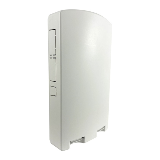
Introduction The ClareOne 16 Zone Hardwired Input Module (HWIM), model number CLR-C1-WD16, allows the takeover of hardwired security zones making them compatible with the ClareOne panel. The HWIM has 16 hardwired zone inputs each with LED status, a tamper switch input, a back-up battery charging terminal, and 2 auxiliary power outputs for powered sensors, capable of outputting 500mA @ 12VDC. - Page 8 Figure 1: ClareOne 16 Zone Hardwired Input Module and main LEDs Processor LED (red color): The Processor LED flashes to indicate processor operation. RF XMIT LED (green color): The RF XMIT LED illuminates when RF transmission is sent. Pairing LED (red color): The Pairing LED illuminates when the HWIM is in “Pairing”...
-
Page 9: Installation
Pair Button: The Pair button puts the HWIM in/out of “Pairing” mode. Installation Only qualified installation technicians should install the HWIM. Clare Controls does not assume responsibility for damages caused by improper installation or use of the device. The HWIM is intended to be mounted to a wall using the included screws and anchors. - Page 10 To install the HWIM: 1. Carefully select the mounting location, verifying that the HWIM’s antennas are pointing up, and then secure it in position using the provided screws and wall anchors. Note: The HWIM should be within 1000 ft (304.8 m) of the panel. Walls, construction materials, and other objects may impede the signal and shorten the distance.
- Page 11 6. Connect the power supply leads from the provided power supply to the terminals labeled +16.0V and GND on the wired input HWIM. Note: The dashed wire is positive. 7. Plug the power supply into a 120VAC outlet. Note: Do not plug the HWIM into a receptacle controlled by a switch. Determining EOL resistance and sensor type Sometimes, it is not visually apparent what is physically connected to a zone in terms of pre-existing EOL resistors and whether the sensor is N/O or N/C.
-
Page 12: Programming
Programming There are two portions of programming involved with the HWIM: adding the HWIM to the panel and pairing zones. Caution: For systems with motion sensors When pairing a zone, tripping any motion sensor that is not already paired to the ClareOne panel causes the motion sensor to pair in instead of the target zone. -
Page 13: Testing
• Motion sensors should be paired first. This includes both wired and wireless motion sensors. 1. If using motion sensors, complete steps 1 through 3 of “To add the HWIM to the panel” on page 6 before continuing. 2. Verify that the HWIM’s Pairing LED is illuminated. If the LED is no longer illuminated, press and hold the Pair button for 2 seconds. -
Page 14: Wiring
Wiring The graphic below details the HWIM wiring. Figure 4: Wiring diagram (1) 12 VDC Backup battery connection (4) 12VDC Auxiliary Power Output 2 (4.a) Positive wire (+) (1.a) Negative wire (-) (4.b) Negative wire (-) (1.b) Positive wire (+) (5) Tamper input (2) 16 VDC Power supply connection (6) Wired zone N/O loop... - Page 15 Note: When wiring a sensor that also has a tamper output, the alarm output and tamper output should be wired in series so that the zone triggers on either an alarm or tamper event. See figure below. 16 Zone Hardwired Input Module...
-
Page 16: Reference Information
Reference information This section describes several areas of reference information that can be useful when installing, monitoring, and troubleshooting an HWIM. Status definitions The ClareOne panel reports the status of the HWIM as Ready by default. Additional HWIM states that may be indicated. Ready: The HWIM is active and is working properly. -
Page 17: Multiple Sensors On A Zone
If the wrong value EOL resistor is used or the EOL resistor is installed incorrectly, the zone will not function properly. This can lead to things such as the zone status being reversed (i.e. reporting open when closed and closed when open). It could also lead to the zone reporting a tampered state or being stuck in a Not Ready state to the ClareOne panel. - Page 18 Figure 8: Multiple powered sensors on one zone Multiple powered sensors on multiple zones For multiple powered sensors on different zones, the sensors should be wired to the zones independently. The power wiring should go directly from the AUX output on the panel to each sensor. Figure 9: Multiple powered sensors on different zones 16 Zone Hardwired Input Module...
-
Page 19: Troubleshooting
Troubleshooting There is a simple sequence of steps that can be taken to troubleshoot most issues that might arise when using the HWIM. The first step before proceeding with troubleshooting is to make sure that the issue is not network related. It is best to troubleshoot the HWIM using the ClareOne panel and not through the ClareHome application, ClareOne Auxiliary Touchpad, or FusionPro. - Page 20 Some powered sensors have a LED to indicate that the sensor is working properly. If the LED on the sensor is functioning when the sensor is triggered, then check the wiring from the HWIM to the sensor. ii. For unpowered sensors, check the wiring from the HWIM to the sensor, including verifying that the EOL resistor is the correct value (4.7 k) and connected properly.
- Page 21 3. Check wiring to and from the HWIM. a. If the power is not connected properly the HWIM will not work. Make sure that the connections are correct and that the supply is plugged into a non-switch controlled active outlet. Use a voltmeter to measure and ensure input voltage to the HWIM is 16VDC.
Need help?
Do you have a question about the ClareOne 16 Zone Hardwired Input Module and is the answer not in the manual?
Questions and answers