Table of Contents
Advertisement
Quick Links
TECHNICAL MANUAL
FOR
MODEL 6564
HIGH RESISTANCE SCANNER
NOTICE
The contents and information contained in this manual are proprietary to Guildline
Instruments Limited.
They are to be used only as a guide to the operation and
maintenance of the equipment with which this manual was issued, and may not be
duplicated or transmitted by any means, either in whole or in part, without the written
permission of Guildline Instruments Limited.
TM6564-C-00
26 April, 2011
Advertisement
Table of Contents

Summary of Contents for Guildline 6564
- Page 1 MODEL 6564 HIGH RESISTANCE SCANNER NOTICE The contents and information contained in this manual are proprietary to Guildline Instruments Limited. They are to be used only as a guide to the operation and maintenance of the equipment with which this manual was issued, and may not be duplicated or transmitted by any means, either in whole or in part, without the written permission of Guildline Instruments Limited.
- Page 3 WARRANTY: This product is warranted against defects in materials and workmanship for a period of one year from date of shipment. During the warranty period, Guildline Instrument Limited will, at its option, either repair or replace products that prove to be defective.
-
Page 4: Table Of Contents
TABLE OF CONTENTS INTRODUCTION ....................1-1 1.1. DESCRIPTION ............................. 1-1 1.2. SPECIFICATIONS ..........................1-2 1.3. REAR PANEL CONNECTIONS ......................1-3 1.4. REFERENCE STANDARD PROTECTION SYSTEMS ..............1-3 INSTALLATION ....................2-1 2.1. INITIAL INSPECTION ........................2-1 2.2. POWER REQUIREMENTS ........................ 2-1 2.3. - Page 5 MAINTENANCE AND TROUBLE SHOOTING ............ 5-1 5.1. PERIODIC MAINTENANCE ......................5-1 5.2. UNSTABLE READINGS ........................5-1 5.3. RELAY FAILURES ..........................5-1 5.4. LOCATING THE RELAY CHANNELS .................... 5-2 CIRCUIT DIAGRAMS AND REPLACEMENT PARTS LIST ........ 6-1 6.1. INTRODUCTION ..........................6-1 6.2.
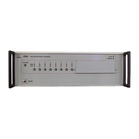
- Page 6 TABLE OF FIGURES FIGURE 1-1 HIGH RESISTANCE SCANNER GUILDLINE MODEL 6564 ..........1-1 FIGURE 3-1 FRONT PANEL GUILDLINE MODEL 6564 ................3-1 FIGURE 3-2 REAR PANEL GUILDLINE MODEL 6564 .................. 3-2 FIGURE 4-1: FUNCTIONAL DIAGRAM OF SCANNER .................. 4-2 TM6564-C-00...
- Page 7 LIST OF TABLES TABLE 3-1: BUS ADDRESS........................... 3-4 TM6564-C-00 26 April, 2011...
-
Page 8: Introduction
General Purpose Interface Bus. The 6564 has been designed in a modular fashion in banks of 8 channels. It is possible to have either 16 channels or 8 channels installed. A cover plate is installed on the front and rear of the 8 channel models covering the channels 9 through 16. -
Page 9: Specifications
Section 1 1.2. SPECIFICATIONS NUMBER OF INPUTS 8 or 16 for Model 6564 ISOLATION ** 700 Peta-Ohms Typical, 100 Peta-Ohms Minimum SYSTEMATIC ERROR DUE CHANNEL VARIABILITY ** Leakage will vary by 3.3% of 100 Peta-Ohms typical, 5% of 100 Peta-Ohms maximum. -
Page 10: Rear Panel Connections
Section 1 1.3. REAR PANEL CONNECTIONS SCANNER INPUTS Low noise High Voltage BNC for voltage source, Low noise Triax for input (low current return). OUTPUT LINES Two low noise N-Type connectors, one each for source and input. INTERFACE BUS 24 pin IEEE-488 connector, CINCH No. 57-20240 REFERENCE STANDARD PROTECTION Screw terminals connected to open collector TTL logic circuit. -
Page 11: Installation
Section 2 INSTALLATION 2.1. INITIAL INSPECTION This instrument was carefully inspected both mechanically and electrically before shipment. It should be free of mars and scratches and in perfect electrical order upon receipt. Unpack the instrument and retain the shipping container until the instrument has been inspected for damage in shipment. -
Page 12: Operation
OPERATION 3.1. FRONT PANEL CONTROLS AND INDICATORS Figure 3-1 Front Panel Guildline Model 6564 1. Line POWER on/off switch 2. LINE A push-button - when depressed will cause any relay on the A line to be cleared. 3. Numbered relay control push-buttons - when depressed at the same time that either the A LINE or the B LINE push-button is depressed will cause the corresponding relay to close. -
Page 13: Rear Panel Connections
Section 3 3.2. REAR PANEL CONNECTIONS Figure 3-2 Rear Panel Guildline Model 6564 1. SCANNER INPUTS - Terminal inputs, Connect BNC terminals to one side of units under test and Triax terminals to the opposite side of the units under test. Numbers correspond to front panel relay numbers. -
Page 14: Front Panel Operation
Section 3 3.3. FRONT PANEL OPERATION The scanner must be in local mode (LOCAL light on) to operate from the front panel. To connect one of the channel inputs to the output proceed as follows: a. Press and hold down the CHANNEL push-button. This will cause any previously closed relay on the CHANNEL to be cleared. - Page 15 Section 3 Interface Board 6 5 4 3 2 1 Position 1 away from board Remote Lock Position 0 switch towards board Address 24 shown ASCII Code Character Address Switches 5 Bit Decimal Listen Talk Code " FACTORY & SETTING <...
-
Page 16: Operation From Interface Bus
Section 3 3.5. OPERATION FROM INTERFACE BUS The interface circuit is designed to accept coded data sent over the bus to actuate the relays. To operate with the bus the scanner must be set to a usable address and must be connected to the controller using a 24 pin IEEE-488 cable (not supplied). -
Page 17: Sample Programs
Section 3 3.6. SAMPLE PROGRAMS The following program will exercise the scanner relays 1 through 16 and leave the line clear. This program is for HTBasic computers with the scanner address set to 724. ! SCANNER TEST DIM Relay$[16] Relay$=”01020304050607080910111213141516” FOR I = 1 TO 16 OUTPUT 724;”A”&Relay$[2*I-1,2*I] ! CLOSES A RELAY... -
Page 18: Remote Lock
Section 3 3.7. REMOTE LOCK The push-buttons can be locked out when it is desired to prevent tampering from the front panel. Position No. 6 of the “DIP” switch located on the Interface printed circuit board is used to lock the scanner in remote only. If the switch is the “O” position (towards the PC board) the REMOTE light will be on and the front panel push-buttons will not operate. -
Page 19: Theory Of Operation
4.1. INTRODUCTION Guildline High Resistance Scanners with extremely low leakage are ideal for automating precision high resistance and low current measurements to ppm accuracy. This versatile scanner a set of shielded high isolation output lines that make it suitable for these applications. -
Page 20: Protection For Devices Connected To The Scanner
PROTECTION FOR DEVICES CONNECTED TO THE SCANNER Some devices such as standard cells can be damaged if two relays on the same output line are closed at the same time. The Guildline Instrument Limited scanners have three methods to protected devices connected to the scanner inputs. - Page 21 Section 4 The second method for protection is the ‘close gate’ lines to the decoder circuits. The control circuit will allow these gates to open only if the series protection line is complete to ground. One of the contacts on each relay is connected in series, and will complete the series protection circuit only if all the relays on the line are in the clear position.
-
Page 22: Maintenance And Trouble Shooting
Section 5 MAINTENANCE AND TROUBLE SHOOTING 5.1. PERIODIC MAINTENANCE There are no adjustments or controls in the scanner. Each relay should be operated at least a 10 times in a given month to ensure they do not become stuck in a fixed position and that the contacts are kept clean. -
Page 23: Locating The Relay Channels
Channels one through four are on the board closest to the power transformer. The next board has channels five through eight and so on. A-Line Relays on Top B-Line Relays on Bottom Low Relays High Relays 6664C Rear Panel 6564 REAR PANEL Figure 5-1 Relay Locations (Top View) TM6564-C-00 26 April, 2011... -
Page 24: Introduction
Section 6 CIRCUIT DIAGRAMS REPLACEMENT PARTS LIST 6.1. INTRODUCTION This section contains circuit diagrams and information for ordering replacement parts. For each circuit board there is a circuit diagram, a component location diagram and a parts list. There is also a list of general parts that are located on the chassis and the rear panel. 6.2. -
Page 25: Circuit Diagrams And Parts Lists
Section 6 6.3. CIRCUIT DIAGRAMS AND PARTS LISTS REAR PANEL PARTS LIST LOCATOR PART PARTS NUMBER NUMBER DESCRIPTION 50-17 POWER JACK CONNECTOR 51-01 LOW THERMAL BINDING POST, BLACK (Tellurium copper gold flashed) 51-02 LOW THERMAL BINDING POST, RED (Tellurium copper gold flashed) 51-03 BINDING POST MOUNTING BASE 51-04... - Page 26 Section 6 A-LINE LOCAL LED REMOTE LED A1 LED B1 LED B-LINE CONNECTOR `A' CONNECTOR `B' CONNECTOR `C' CONNECTOR `D' MODEL 164B, 6664B SWITCH BOARDS (ALL) PARTS LIST CIRCUIT PART PARTS DESIG. NUMBER DESCRIPTION all LED's 23-01 LIGHT EMITTING DIODE, Red SWITCHES 31-02 SWITCH, Pushbutton, SPDT...
- Page 27 Section 6 6564 FRONT PANEL CIRCUIT DIAGRAM Connector A Connector B LINE A To A1 Relay A1 LED 180 Ohm To A9 Relay A9 LED 180 Ohm LINE B Switch 9 To B1 Relay B1 LED 180 Ohm To B9 Relay...
- Page 28 Section 6 LS123 LS123 LS123 LS20 LS20 LS00 LS32 LS11 LS00 LS148 LS148 LS157 LS148 LS148 LS14 LS139 LS157 LS05 33 F + CONTROL BOARD COMPONENT LOCATIONS CONTROL BOARD CIRCUIT PARTS LIST CIRCUIT PART PARTS DESIGN. NUMBER DESCRIPTION C4,5,8-10,12-15 16-02 CAPACITOR, FXD, .01 uFd 50VDC, 10%, Monolithic C1,2,3,6,7 18-01...
- Page 29 Section 6 FROM BUS INTERFACE TO CLOSE BOARDS TO FRONT PANEL PUSH BUTTONS ON SW ITCH BOARD TM6564-C-00 26 April, 2011...
- Page 30 Section 6 TM6564-C-00 26 April, 2011...
- Page 31 Section 6 ADRESS INTERFACE BOARD COMPONENT LOCATIONS INTERFACE BOARD CIRCUIT PARTS LIST CIRCUIT PART PARTS DESIGN. NUMBER DESCRIPTION C3,4,5,6 16-01 CAPACITOR, FXD, 470 pf 50VDC, 5%, Monolithic C1,2,7,8 16-02 CAPACITOR, FXD, .01 uFd 50VDC, 10%, Monolithic 18-04 CAPACITOR, FXD, .33 uFd 10VDC, 10%, Tantalum C10-13 18-02 CAPACITOR, FXD, 3.3 uFd 15 VDC, 10%, Tantalum...
- Page 32 Section 6 GPIB Interface Board Curcuit Diagram 320A-007E TM6564-C-00 26 April, 2011...
- Page 33 Section 6 CLOSE BOARD COMPONENT LOCATIONS Notes: Two close boards are used in Model 6564 Diodes (CR1-CR32) not used with +5V relays CLOSE CIRCUIT PARTS LIST CIRCUIT PART PARTS DESIG. NUMBER DESCRIPTION C1,C2 16-02 CAPACITOR, FXD, .01 uFd 50VDC, 10%,...
- Page 34 Section 6 RELAY CHANNEL 1A 2.2k RELAY LS175 CHANNEL 2A 2.2k FLIP FLOP RELAY CHANNEL 3A 2.2k RELAY CHANNEL 4A 2.2k RELAY CHANNEL 5A 2.2k RELAY LS175 CHANNEL 6A 2.2k FLIP FLOP RELAY CHANNEL 7A 2.2k RELAY CHANNEL 8A 2.2k LINE A PROTECT IN LINE A PROTECT OUT LINE A CLEAR PULSE...
- Page 35 Section 6 OPEN BOARD COMPONENT LOCATIONS Notes: Four Open Boards are used in Model 6564 Diodes (D1-D16) not used with +5V relays OPEN CIRCUIT PARTS LIST (Rev. B) CIRCUIT PART PARTS DESIG. NUMBER DESCRIPTION C1,C2 16-02 CAPACITOR, FXD, .01 uFd 50VDC, 10%, Monolithic...
- Page 36 Section 6 CHANNEL 1A 1000 LS175 CHANNEL 2A FLIP 1000 FLOP CHANNEL 3A 1000 CHANNEL 4A 1000 CHANNEL 5A 1000 CHANNEL 6A LS175 1000 FLIP FLOP CHANNEL 7A 1000 CHANNEL 8A 1000 LINE A PROTECT IN LINE A PROTECT OUT LINE A CLEAR PULSE RN1, 1k LS123...
- Page 37 Section 6 INPUT 1 INPUT 2 INPUT 3 INPUT 4 OUTPUT A OUTPUT B 1A RELAYS 2A RELAYS 3A RELAYS 4A RELAYS 1B RELAYS 2B RELAYS 3B RELAYS 4B RELAYS RELAY BOARD COMPONENT LOCATIONS Notes: Each Board holds latching relays for four channels of low thermal inputs. Four or eight boards are used depending on the model These boards are located under the top of the isothermal box.
- Page 38 Section 6 (164B / 6664B "P") INPUT 1 RELAYS (164B / 6664B "C") RELAYS 1B LIGHT 1B CLEAR 1B CLOSE 1A LIGHT 1A CLEAR 164B / 6664B "P") 1ACLOSE INPUT 2 RELAYS (164B / 6664B "C") RELAYS 2B LIGHT 2B CLEAR 2B CLOSE 2A LIGHT 2A CLEAR...
-
Page 39: Declaration Of Conformity
Section 7 DECLARATION OF CONFORMITY (According to ISO/IEC Guide and EN 54014) Manufacturer’s Name: Guildline Instruments Limited Manufacturer’s Address: 21 Gilroy St. Smiths Falls, Ont. K7A4S9 Declares, the product Product Name: High Resistance Scanner 6564 Model Numbers: All Options Product Options:...
Need help?
Do you have a question about the 6564 and is the answer not in the manual?
Questions and answers