Table of Contents
Advertisement
Quick Links
Advertisement
Table of Contents

Related Manuals for Schonstedt Instrument XTpc-33

Summary of Contents for Schonstedt Instrument XTpc-33
- Page 1 Instruction Manual Model XTpc Pipe & Cable Locator Product Line Manufactured By Schonstedt Instrument Company 100 Edmond Road Kearneysville, WV 25430 (304) 725‐1050 Fax (304) 725‐1095 Web: www.schonstedt.com E‐mail: info@schonstedt.com Made in USA January 2017 ...
- Page 2 Important Notice Schonstedt believes the statements contained herein to be accurate and reliable; however, their accuracy, reliability, or completeness is not guaranteed. Schonstedt's only obligation shall be to repair or replace any instrument proven to be defective within three years of purchase. Schonstedt shall not be responsible for any injury to persons or property, direct or consequential, arising from the use of any instrument. This device complies with part 15 of the FCC Rules. Operation is subject to the following two conditions: (1) this device may not cause harmful interference, and (2) this device must accept any interference received, including interference that may cause undesired operation. Application of Council Directive(s): ...
-
Page 3: Table Of Contents
Table of Contents SECTION I: OPERATING MODES Passive 50/60 Hz (P) ........................ 4 Passive Cathodic (PC) ........................ 4 Conductive (C) .......................... 4 Inductive Clamp (IC) ........................ 4 Inductive (I) ........................... 5 Sonde (S) ............................ 5 SECTION II: THE XTpc PRODUCT LINE Products Covered By This Manual .................... 6 Model Comparison Chart ...................... 7 ... -
Page 4: Section I: Operating Modes
SECTION I: OPERATING MODES Pipe and cable locators in general can operate in a variety of modes and frequencies. The following is a brief description of the basic operating modes supported by the XTpc line of pipe and cable locators, and it is not intended to be a comprehensive locating tutorial. For additional information on pipe and cable locating theory and techniques, refer to Schonstedt’s training section online at www.schonstedt.com. Passive 50/60 Hz (P) In the passive mode, the transmitter is not used at all. Instead, the receiver searches for an appropriate harmonic of 60 or 50 Hz signals (factory preset). These signals are typically present in energized ... -
Page 5: Inductive (I)
Inductive (I) In the inductive mode, the transmitter imposes a signal of the "active" frequency onto the pipe or cable to be traced. It does so by radiating a signal through the inductive antenna, which is placed on the ground in a direction perpendicular to the pipe or cable being traced. The inductive antenna then induces a current onto the pipe or cable. In this mode, it is not necessary to provide a return path for the induced current to the transmitter. The induced current will travel on the pipe or cable for a distance making it possible to trace it. ... -
Page 6: Section Ii: The Xtpc Product Line
SECTION II: THE XTPC PRODUCT LINE While emphasizing portability, size, and convenience, the XTpc line of pipe and cable locators offers several choices to suit almost any type of locating challenge. The unique ability of XTpc locators to collapse (for portability) and expand (for greater sensitivity and full functionality) is unparalleled in the industry. In the design our locators, Schonstedt has incorporated more than sixty years of experience in producing the world's finest locating products for aerospace, military and civilian applications. All Schonstedt ... -
Page 7: Model Comparison Chart
The next section provides a quick comparative overview of the main features and characteristics of each of these locators. Detailed operation is covered elsewhere in the text. Model Comparison Chart Model P PC C IC(1) I(2) S (freq.) TX Freq. Depth XTpc‐33 Y N Y Y Y Y (33 kHz) 33 kHz Y XTpc‐33‐PC Y Y Y Y Y N 33 kHz Y XTpc‐33‐512 Y N Y Y Y Y (512 Hz) 33 kHz ... -
Page 8: Depth Measurement
Depth Measurement XTpc receivers have the ability to measure the approximate depth of the target pipe or cable being traced. The bottom tip of the receiver must touch the ground when depth measurement is made, and best results are obtained when the receiver is in a fully extended position. Depth measurements should only be made when the directional indication says that the target is directly below the receiver and the signal strength is adequate. Special considerations are required for the Sonde mode (see SECTION VIII: OPERATING RECOMMENDATIONS for details). Automatic and Manual Output Power The transmitters of the XTpc line of pipe and cable locators deliver power to the "load" connected to ... -
Page 9: Transmitter Time Out
mode of operation. The resistance measurement provides an additional indication of the quality of the locating circuit. Transmitter Time Out The transmitters of the XTpc line of pipe and cable locators will turn themselves off, under the conditions listed below, to protect the battery from an extremely deep discharge: A) All transmitters: When ... -
Page 10: Section Iii: Operating Controls
SECTION III: OPERATING CONTROLS The product controls are designed to be intuitive and require a minimum of training for effective use. The receiver can easily be operated with one hand. The transmitter automatically recognizes which accessory is plugged in, requiring no adjustments in the inductive and inductive clamp modes. Receiver A) All Models: ON/VOLUME ‐ This switch powers on the receiver and automatically sets the volume to High. Additional depressions of this switch will cycle the volume through Off (no sound), Medium, and High settings. OFF ‐ This switch removes power from the receiver. UP/DOWN Arrows ‐ When the receiver is operating in manual gain mode, pressing the UP or DOWN arrows will increase or decrease the gain from its current setting. When the receiver is operating in the automatic gain mode, the first press of the UP or DOWN arrow will switch the receiver to the manual gain mode. ... -
Page 11: Transmitter
B) All models EXCLUDING XTpc+ : PASSIVE ‐ If the receiver is not operating in passive mode, pressing this switch will cause the receiver to go to the passive mode of operation. If the receiver is already operating in passive mode, pressing this switch will cause the receiver to stop the passive mode of operation. PC ‐ If the passive cathodic mode is available and the receiver is not operating in passive cathodic mode, pressing this switch will cause the receiver to go to the passive cathodic mode of operation. If the receiver is already operating in passive cathodic mode, pressing this switch will cause the receiver to stop the passive cathodic mode of operation. C) XTpc+ model ONLY: ... - Page 12 OUTPUT POWER ‐ This switch is used to manually select the output power in the conductive mode only. It has no use in the inductive and inductive clamp modes, where the output power is internally fixed. Each press increases the output power as follows: P‐L (1/2 watt) >> P‐1 (1 watt) >> P‐2 (2 watts) >> P‐5 (5 watts) >> P‐L (1/2 watt), and so on. At the 82 kHz operating frequency, only 1/2 and 1 watt are available (due to FCC regulations). ...
-
Page 13: Section Iv: Visual And Audible Indicators
SECTION IV: VISUAL AND AUDIBLE INDICATORS The information display areas for the receiver and the transmitter are large and easy to understand. In addition, the receiver has audible indicators to facilitate operation in heavy traffic areas. Receiver All visual indicators for the receiver are on the LCD display, which has six general areas to display information to the user: a Battery Indicator, a Gain Indicator, a Frequency/Mode Indicator, a Direction Indicator, an Alphanumeric Display and a Volume Indicator. BATTERY INDICATOR ‐ The "Battery" symbol indicates the receiver's battery status. When all 3 segments inside the battery symbol are present, the battery is fully charged. When only the 2 bottom segments are present, the battery has a medium charge. When ... - Page 14 All models EXCLUDING XTpc+: SONDE 33 kHz 82 kHz PASSIVE ARROW C, IC, I at 33 kHz Off Off C, IC, I at 82 kHz Off Off On Off Sonde at 33 kHz On On Off Off Sonde at 82 kHz On Off On Off Passive 50/60 Off Off Off On Passive Cathodic (*) On Off On Off Sonde at 512 Hz On Off Off Off (*) Models with Passive Cathodic support do not support sondes ...
-
Page 15: Transmitter
ALPHANUMERIC DISPLAY ‐ The alphanumeric display is used to display signal strength and depth. On XTpc+ models, the numeric display is also used for temporary indications of certain operating modes, frequencies (see table on page 14), and other brief information messages. Signal Strength ‐ This is an indication of the relative signal level detected by the receiver and is a function of the gain setting. Good signal strength will typically be between 200 and 800. The display range for signal strength is 0 to 999; however, a very high signal strength is not necessarily better. If readings of 995 or higher are consistent, the signal is too strong and steps should be taken to reduce it. If a reading of “OL” is observed, a signal is present which interferes with the signal the receiver is set to detect. Steps should be taken to identify the source of interference or to change the locating mode. ... - Page 16 BATTERY INDICATOR ‐ The "Battery" symbol indicates the transmitter's battery status. When all 3 segments inside the battery symbol are present, the battery is fully charged. When only the 2 bottom segments are present, the battery has a medium charge. When only the bottom segment is present, the battery has a low charge and should be recharged as soon as possible. If there are no segments present, the battery is extremely low and it should be recharged immediately. If the battery reaches a voltage dangerously close to the level when continuous operation can damage it, the empty battery ...
- Page 17 Accessory Plugged In Operating Mode Mode Indicator None Non operational ‐ Numeric Display Legend says "On" Idle Battery Symbol = Lit Frequency Indicator = Lit Arrow indicators pointing to mode printed on the faceplate, along the right side edge of LCD, are all flashing Battery Charger Non operational – Numeric Display Legend says "CHA" Charging Battery Symbol = Rolling bars inside battery box Frequency Indicator = Lit Arrow indicators = All OFF Conductive Clips Conductive Numeric Display Legend = Shows output current in mA Battery Symbol = Lit Frequency Indicator = Lit Arrow indicator = Pointing to CONDUCTIVE Inductive Clamp Clamp Numeric Display Legend says "CLP" Battery Symbol = Lit Frequency Indicator = Lit Arrow indicator = Pointing to CLAMP Inductive Antenna Inductive Numeric Display Legend says "Ind" Battery Symbol = Lit Frequency Indicator = Lit Arrow indicator = Pointing to INDUCTIVE B) XTpc+ model ONLY (the Tx5 transmitter): ...
- Page 18 UNITS INDICATORS ‐ During normal operation, or when the Tx5 transmitter is measuring line voltage and resistance, it is necessary to display information to the user with the appropriate units. The indicators on the LCD are as follows: Ω Ohms, a resistance measurement unit kΩ kilo‐Ohm = 1000 Ohms MΩ Mega‐Ohm = 1,000,000 Ohms A Ampere, an electrical current measurement unit mA milli‐Ampere = 1/1000 Ampere Hz Hertz, a frequency measurement unit kHz kilo‐Hertz = 1000 Hertz ...
-
Page 19: Section V: Connectors And Accessories
SECTION V: CONNECTORS AND ACCESSORIES Receiver Connector The 3.5mm headphone jack accepts any mono or stereo earphones or headphones. The receiver automatically detects the insertion of the plug and routes the audio signals to the earphones or headphones, silencing the internal speaker. Transmitter Connector A) All models EXCLUDING XTpc+: ... -
Page 20: Standard Accessories
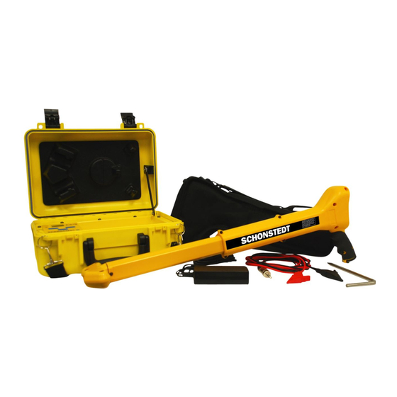
Standard Accessories The following accessories are included with ALL models EXCLUDING XT‐512: Belt receiver holder cup Ground stake Conductive clips Universal power supply for battery charger with power cord In addition, the following accessories are included, depending on the model: A) All models EXCLUDING XT‐512 and XTpc+: Hard carrying case Battery charger with power cord for Transmitter Battery Vehicle power supply adapter for battery charger Headphone jack plug B) XT‐512 and XTpc+ models ONLY: Soft carrying bag Headphone jack plug Optional Accessories Many optional accessories are available for the XTpc pipe and cable locator line. The following list includes the most common ones. Please contact Schonstedt or your local dealer for details. ... -
Page 21: Section Vi: Batteries And Charger
SECTION VI: BATTERIES AND CHARGER Receiver Battery The XTpc receiver is powered by one 9‐volt disposable battery. The battery is located in the handle of the instrument and can be accessed by turning the screw counterclockwise. To remove the battery, simply tilt the unit so that the handle is pointing down, and the battery will slide out. When replacing the battery, look at the inside of the battery door for the proper battery orientation. As a safety measure the unit will not turn on if the battery is not inserted correctly. You should never have to force the battery door closed. If the battery does not seem to be going in all the way, remove the ... -
Page 22: Battery Charger Indicators
The vehicle power supply, included with all XTpc models except the XTpc+, allows the battery to be recharged while driving from job to job. For the XTpc+ transmitter (the Tx5) an alternative for in‐ vehicle charging is to plug the AC power supply into one of the many commercially available vehicle DC‐to‐AC inverters capable of supplying at least 100 W of power. Battery Charger Indicators A) All transmitters EXCLUDING the XTpc+ (Tx5): After plugging the charger into the XTpc transmitter and connecting the AC power to it, allow a few minutes for it to settle. The LED indicators are as follows: FULL (Green): The charger has determined that the battery is fully charged CHARGING (Yellow): The charger is charging the battery FAULT (Red): See explanation below Conditions Under Which the FAULT LED Will Come On: The FAULT LED indicates that the battery charger is not charging the battery successfully. This can be for a number of reasons: the battery may be overcharged, the battery may not be taking a charge in a reasonable amount of time, the battery may be too warm to be charged without causing damage to its internal cells, or the battery charger may have an internal fault. ... -
Page 23: Recommendations For Battery Charging And Storage
B) XTpc+ ONLY (the Tx5 transmitter): When the Tx5 transmitter detects that the battery charger is plugged in, and if the power is turned ON, it will display “bAt CHA” on the LCD and the bars inside the battery indicator will “roll”. When the battery is fully charged, it will display “bAt FUL” on the LCD, as shown below. If the power is OFF, the battery will still charge, but no indication of charging activity or battery status will be shown on the LCD. If the battery charger is not charging the battery successfully, the following indication will be shown on the LCD: This can be for a number of reasons: the battery may be overcharged, the battery may not be taking a charge in a reasonable amount of time, the battery may be too warm to be charged without causing damage to its internal cells, or the battery charger may have an internal fault. ... - Page 24 Before normal charging can begin, the battery pack temperature and voltage must fall within predetermined acceptable limits. The temperature must be between 50° and 104° F (10° and 40° C). When the charger detects that these two conditions are not met, it will continue to “trickle charge” until the two conditions are met. Then, it will start normal charging. If the battery if faulty and it never reaches acceptable voltage to start normal charging, the charger continues to trickle charge. In this case, only a small fraction of full charge will be reached after the normal 4‐hours of charging time. If the charger is charging the battery in normal charge mode and the temperature rises above 140° F (60° C) before the battery is fully charged, the charger will switch to trickle charge mode. In this case, full charge may not be achieved after the normal 4‐hours of charging time. The battery pack also contains a thermostat that will open the circuit for safety if it gets too hot. ...
-
Page 25: Section Vii: Specifications
SECTION VII: SPECIFICATIONS (Specifications are subject to change without notice) Receiver Operating Frequency: Active and passive frequencies depending on model (see Model Comparison Chart) Battery: 9V Alkaline single battery Battery Life: 12 hours (intermittent use) Audio Output: 10 ‐ 1500 Hz (determined by signal strength) 0 ‐ 70 db SPL (Sound Pressure Level), volume controlled Weight (incl. batteries): Under 2.8 lbs Operating Temp.: ‐4°F to 140°F (‐20°C to 70°C) Water and Dust Resistance Rated IP54, when operated with earphone jack plug (provided) Overall Dimensions: Closed: 17.5 in x 3 in x 8.5 in (44 cm x 7.6 cm x 21.5 cm) Extended: 27.7 in x 3 in x 8.5 in (70 cm x 7.6 cm x 21.5 cm) Max. Depth Capability: Approximately 19' (5.8 m) Sonde mode approximately 5'‐ 8' (1.5 m ‐ 2.5 m) ... - Page 26 Battery Type: Rechargeable NiMH pack (7.2V) Battery Life: 8 hours (intermittent usage @ 70° F) Charging: External smart charger powered by AC/DC power adapter (100‐240 V ‐ 0.8 A), or vehicle supply Outputs/Inputs: Circular "smart" connector to: 1) Inductive antenna (output) 2) Inductive clamp (output) 3) Conductive clips (output) 4) Battery charger (input) Dimensions: 7.2” W x 2.2” D x 1.5” H (18.3 cm x 5.6 cm x 3.8 cm) Weight: 1.5 lbs. (0.68 kg) Operating Temp.: ‐4°F to 140°F (‐20°C to 70°C) Backlighting: N/A B) XTpc+ ONLY (the Tx5 transmitter): ...
- Page 27 Outputs/Inputs: a) Phono plug output connector to: 1) Inductive clamp 2) Conductive clips b) 5.5 mm x 2.1 mm DC jack input connector, center positive, from: 1) AC/DC power adapter (100‐240 V ‐0.8 A) 2) 22‐30 VDC, 1.5 A supply Dimensions: 14” W x 10.5” D x 6” H (35.5 cm x 27 cm x 15 cm) Weight: 9.1 lbs. (4.1 kg) Operating Temp.: ‐4°F to 140°F (‐20°C to 70°C) Backlighting: White LED array, ambient light sensing Environmental: IP56 per ANSI/IEC 60529‐2004 MIL‐STD‐810 F 27 ...
-
Page 28: Section Viii: Operating Recommendations
SECTION VIII: OPERATING RECOMMENDATIONS Follow these tips and recommendations to operate your XTpc Pipe and Cable Locator: 1) Whenever possible, use the conductive mode. It provides the strongest and best‐coupled signal. 2) When operating in conductive mode: The ground stake should be buried on a line perpendicular to the utility to be traced and as far from it as possible. Verify that a good circuit has been established by checking the output current from the transmitter. If necessary, make adjustments to the ground stake or clips to improve the connection. You can also manually adjust the output power to affect the output current. 3) When operating in the inductive mode, place the antenna (an additional accessory for the XTpc model but is built into the transmitter of the XTpc+ model) over the buried cable or pipe in the direction indicated by the label. (This application does not apply to XT‐512, which is a receiver only device.) ... - Page 29 Figure 1: Showing receiver orientation Figure 2: Showing receiver orientation in in “NULL” or lowest signal strength “Peak” ...
-
Page 30: Section Ix: Technical Support
SECTION IX: TECHNICAL SUPPORT Schonstedt offers technical support and sales support. For any reason regarding usage and application, please contact our technical support team at 888‐32‐TRACE (888‐328‐7223). FOR SERVICE OR REPAIR Please ship unit to: Schonstedt Instrument Company 100 Edmond Road Kearneysville, WV 25430 Attn: Customer Service Dept. SECTION X: WARRANTY INFORMATION Schonstedt Instrument Company (Schonstedt) warrants each product of its manufacture to be free from ...
Need help?
Do you have a question about the XTpc-33 and is the answer not in the manual?
Questions and answers