Advertisement
Quick Links
1. Purpose
Digital-to-analog converter unit «DAC-40-USB» is intended to provide
multi-channel voltage output. It is controlled from a personal computer via a USB
port. Its primary purpose is to drive deformable mirrors produced by OKO
Technologies.
2. Specifications
Analog outputs
Output range
Output resolution
Range of adjustment of the maximum
output voltage
Ohmic load, each channel
Load capacitance, each channel
Synchronous output for all channels.
Power is provided via the USB port.
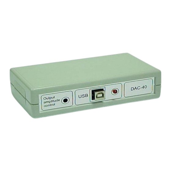
3. General design
«DAC-40-USB» is designed as a PCB with two double-row angle
connectors BH-20R (male) and a B-type USB connector; it is mounted in a
compact housing. Pins of the output connectors are labeled according to the
OKO Tech DAC40 USB
DAC unit «DAC-40-USB»
Manual
V 1.0
40
0 – 5.5 V
12 bits (4096 levels)
2.5 – 5.5 V
≥100 kΩ
≤500 pF
V 2.0
40
0 – 5.0 V
2.6 – 5.0 V
≥100 kΩ
≤500 pF
1
Advertisement

Summary of Contents for Okotech DAC-40-USB
- Page 1 Power is provided via the USB port. 3. General design «DAC-40-USB» is designed as a PCB with two double-row angle connectors BH-20R (male) and a B-type USB connector; it is mounted in a compact housing. Pins of the output connectors are labeled according to the...
- Page 2 To close the housing, the decks must be pushed vertically one to another till latched. Fig. 1. «DAC-40-USB» view from the output connectors’ side Fig. 2. «DAC-40-USB» view from the USB connector side 3.1.
- Page 3 Jumpers JP2 and JP3 are mounted on the PCB (Fig. 3). By connecting contacts 2 and 3 of jumpers JP2 and JP3 pin #1 of connector X3 (channel 1) and/or pin #1 of X4 (channel 21), correspondingly, can be connected to the ground (see Table 1).
- Page 4 Table 2 Jumper settings and output connectors commutation Pin 1 of X5 Pin 2 of X5 Pin 1 of X6 Pin 2 of X6 1–2 Ch #1 output Ch #2 output 1–2 Ch #21 output Ch #22 output direct direct 2–3 Ground Ch #2 output...
- Page 5 Appendix 2. For synchronous control of the units one may use the function MakePacket. It is implied that before this all devices «DAC-40-USB» are opened by means of the function FT_Open, with preliminary defined system numbers of these modules.
- Page 6 7. Calibration of the unit Using the DAC unit it is necessary to keep in mind that the minimum voltage generated by any output channel corresponds, in general case, to non-zero control code. It is due to specifics of operation of the DAC chip. User can set the minimum value of this parameter for each channel by adjustment of the maximum output voltage .
- Page 7 7, 15, 23, 31, 39, //| 6, 14, 22, 30, 38, //| 5, 13, 21, 29, 37, //| 4, 12, 20, 28, 36, //| 3, 11, 19, 27, 35, //| 2, 10, 18, 26, 34, //| 9, 17, 25, 33, //| 8, 16, 24, 32 //--------------------------------------------------------------------------- void MakePacket(WORD *buf,BYTE *packet)
- Page 8 // FT_ListDevices OK, serial number is in Buffer else { // FT_ListDevices failed This sample shows how to get the product descriptions of all the devices currently connected. FT_STATUS ftStatus; char *BufPtrs[3]; // pointer to array of 3 pointers char Buffer1[64]; // buffer for the product description of first device found char Buffer2[64];...
- Page 9 Supply power to the amplifier boards (units) as specified in the mirror manual. • Connect «DAC-40-USB» to the computer using a USB cable. Turn on the low voltage power supply, then the high voltage one. • The folder /mmdm37ch_vc of the software CD contains simple command- line utilities for control of the mirror, which are compiled with Visual C++ 6.0.
- Page 10 /mmdm37ch_vc, enter it in the command line and type “nmake”. 9. Using with other deformable mirrors The CD suipplied with «DAC-40-USB» also contains sample control programs for other deformable mirrors from OKO Technologies. These programs include “am_set”, “rotate” and “set_channel” utilities similar to those described in Section 8.
Need help?
Do you have a question about the DAC-40-USB and is the answer not in the manual?
Questions and answers