Table of Contents
Advertisement
Quick Links
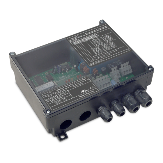
SGC 11 - USER MANUAL
Space Guard Series
Photoelectric light curtain controller
Product Data
Electrical Data
ac
Supply voltage
dc
ac
Voltage tolerance
dc
Current consumption
Relay
Output
Transistor NPN
Environmental Data
Temperature, operation
Sealing class
Approvals
Available Models
Model
300
301
302
SGC 11 A
500
501
502
Note:
1. Detectors to be ordered separately.
2. All controllers can be used with a 24 V dc supply voltage.
Connection
Wiring Diagrams
Relay and NPN output
Relay output
Installations & Adjustments
Installation
Connect the SGR detector to the RX connector input and the SGT detector to the
1
TX connector input.
Connect either AC power supply to the terminals marked 0 and 2, or connect 24 V
2
dc power supply to the terminals marked + and -. DO NOT turn power on.
Warning: DO NOT connect AC and DC power supply at the same time
3
Connect terminal
to earth or machine frame.
Connect to relay on terminal NO, COM, NC or to transistor output on terminal SIG
4
(signal),
(ground) according to your application. For "safety" relay operation use
NO and COM outputs.
Connect to the Alarm and Time-out outputs on terminals AL, TO and
5
to your application.
6
Turn the gain potentiometer to max sensitivity (fully clockwise).
Make sure Operation Mode (SW2 DIP-switch nº 2 : OFF) has been selected. Make
7
sure Long Range has been selected (SW2 DIP-switch nº1 : ON).
Turn power on after double checking your wiring, and checking for correct power
8
supply voltage.
Website: www.telcosensors.com
E-Mail:
info@telcosensors.com
Made in Denmark
24 V ac, 115 V ac or 230 V ac
24 V dc
-12 % / + 6 %
+/- 15 %
Max. 15 VA
1 open / 1 close, 250 V ac / 3 A, 120 V ac / 5 A
Max. 24 V dc / 100 mA
-10 to + 40 ºC
IP 20
Supply Voltage
Output
230 V ac
115 V ac
Relay and NPN
24 V ac
230 V ac
115 V ac
Relay
24 V ac
dc-supply
ac-supply
Relay output
24 VDC
AC
SUPPLY
SUPPLY
dc-supply
ac-supply
Relay output
24 VDC
AC
SUPPLY
SUPPLY
!
This device is not to be used for Personnel Protection in Machine
Guarding Safety applications. This device does not include the self-
checking redundant circuitry necessary to allow its use in personnel
machine guarding stand-alone safety applications.
EN
If the controller indicates a broken beam despite a clear optical path between the
detectors, switch to Diagnostic Mode. Wait approx. 15 sec. The RXERR and
9
TXERR LED's will indicate the faulty detector. Change or clean the faulty detector
and switch to Operation Mode.
For operation at ranges below approx. 3 m it is recommended to adjust the
sensitivity, following the calibration procedure below.
10
Turn the potentiometer to minimum (fully anticlockwise), and then turn slowly
clockwise until the detector see each other. If the adjustment appears too delicate,
then switch to Short Range and re-adjust.
In applications with operation at short range it is recommended to use Automatic
Sensitivity Control Mode, to ensure that the light beams easily can be broken. If
11
there is a need for constant excess emitted power at short range, use Fixed
Sensitivity Mode.
12
Select Relay Mode and time-out according to your application.
Output Logic
Detection
Present
Absent
Long/Short Range Selection
Long range
Short range
Diagnostic/Operation Mode
Diagnostic
mode
Operation
mode
Automatic Sensing/Fixed Sensing
Automatic
Sensing
Control
Fixed Sensing
Buzzer On/Off
Buzzer On
Buzzed Off
Time-out function
according
After one or more beams (selectable from 0 to 32) have been broken for more than a preset
period of time (selectable from approx. 15 seconds to 10 minutes) the Controller
will ignore the broken beams, and thus allow the system to operate with the remaining light
beams.
The maximum number of channels time-out can be
selected from 0 to 32 by using the DIP-switches nº 1,2 and
3, on the SW1 switch. Please, refer to Fig. 1
The time-out delay time can be selected from approx. 15
seconds to 10 minutes by using the DIP-switches nº 5,6
and 7, on the SW1 switch. Please, refer to Fig. 1
Warning
Output
Relay
mode
Dark
NC
C
NO
operated
Light
NC
C
NO
operated
NC
C
NO
Dark
operated
Light
NC
C
NO
operated
Enables the system to operate at 100% (maximum
range). Range up to 5 m.
Enables the system to operate at 60% of maximum
range. Range up to 3 m.
This switch is only for service. When activated, the
controller initiates a self test. If there is any error in
transmitter or in the receiver, the TXERR LED or
RXERR LED are activated. For instance,
contamination on detectors, bad connections,...
Operating mode.
Automatic Sensitivity Control Mode is
recommended in applications with operation at
short range, to ensure that the light beams easily
can be broken.
Allows to adjust manually the sensitivity of the
system via the potentiometer.
Activates the buzzer in parallel with the output.
Deactivates the buzzer.
Telco A/S reserves the right to make changes without prior notice
tel
Output
Transistor
indicator
Output
(yellow led)
Closed
On
Open
Off
Open
Off
Closed
On
SW2
SW2
SW2
SW1
V 1.1 Part Number: 0666220649
April 2019 edition
Advertisement
Table of Contents

Summary of Contents for Telco Sensors Space Guard SGC 11
- Page 1 SGC 11 - USER MANUAL Space Guard Series Photoelectric light curtain controller Product Data If the controller indicates a broken beam despite a clear optical path between the detectors, switch to Diagnostic Mode. Wait approx. 15 sec. The RXERR and Electrical Data TXERR LED’s will indicate the faulty detector.
- Page 2 SGC 11 - USER MANUAL Space Guard Series Photoelectric light curtain controller Output Mode Selection Time-out indicator (red led): Activated when one or more channels are timed out. Enables the output to be inactive (yellow Alarm indicator (red led): Activated when the number of channels timed out is Light Operated LED is off) when there is an object present greater than –...
Need help?
Do you have a question about the Space Guard SGC 11 and is the answer not in the manual?
Questions and answers