Advertisement
Quick Links
Advertisement

Summary of Contents for Altechna VBE 1X-4X
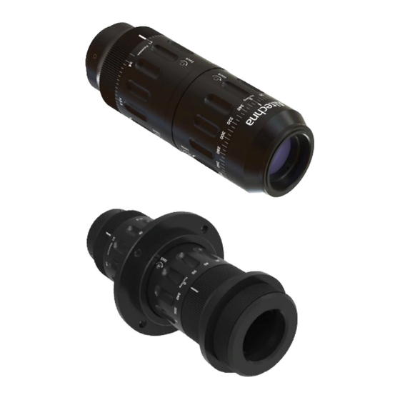
- Page 1 Variable Beam Expander 1X-4X User Manual 2020 version v.1.00...
-
Page 2: Table Of Contents
Contents 1. Introduction 2. Applications 3. Technical information 4. Alignment 5. Usage... -
Page 3: Introduction
(including damages for loss of profits, loss of business, loss of use or data, interruption of busines and the like), even if Altechna has been advised of the possibility of such damages arising from any defect or error in this manual or product. -
Page 4: Applications
2. Applications Laser beam size control Control of focusing parameters (Numerical Aperture) 3. Technical information Expansion ratio: 1x-4x Input aperture: 11 mm Exit aperture: 19 mm Lens material: UVFS Total transmission: >97% Wavefront distortion: <λ/4 @ 632.8 nm LIDT: >10 J/cm² @ 1064 nm, 10 ns, 10 Hz Housing dimensions: Ø41.5 x 120-136.7 mm Mounting thread: SM1 Magnification... -
Page 5: Alignment
4. Alignment To obtain optimal performance it is highly recommended to align the VBE with input laser beam. VBE alignment procedure: 1. Install camera ~1200 mm from the laser output, center it and set current beam position as a reference point by placing crosshair over the center (fig. - Page 6 5. Set VBE expansion scale to “x4” and focusing scale cylinder most counter-clockwise so that sliding cylinder at the output of VBE was most outwards, it should correspond to ~260° mark on the scale (fig. 3): Setting the focusing most outwards. Figure 3.
- Page 7 7. Set VBE expansion scale to “x1”and focusing scale to number “0°” (fig. 5): Setting VBE expansion and focusing. Figure 5. 8. After magnification and focusing are changed, the laser beam spot will be decentered on the screen again. 9. Set current beam position as a reference point by placing crosshair over the center (fig. 6): à...
-
Page 8: Usage
Setting expansion and focusing. Figure 7. 11. The laser beam spot will be moved from the crosshair again. By adjusting tilt (θx; θy) get the laser beam spot back to the crosshair (fig. 8): Centering laser beam sport with crosshair. Figure 8. - Page 9 2. Expansion cylinder should be rotated so that desired magnification value on the scale is aligned with reference mark. 3. Focusing cylinder should be rotated to match the angle on focusing scale as per graph below. Please note, that collimation curves are different for different wavelengths (fig. 9). Collimation curves 250°...
- Page 10 Collimation curves 240° 200° 160° 120° 80° Ø2 mm beam Ø4 mm beam 40° Ø6 mm beam 0° 1.5x 2.5x 3.5x Expansion ratio (times) Collimation curves. Figure 10. 5. Depending on input beam divergence, collimation might require extra tuning, especially on the lower expansion end.
- Page 12 Tel. +370 5 272 5738 Fax +370 5 272 3704 info@altechna.com Mokslininku st. 6A Vilnius, Lithuania www.altechna.com...
Need help?
Do you have a question about the VBE 1X-4X and is the answer not in the manual?
Questions and answers