Table of Contents
Advertisement
Quick Links
Advertisement
Chapters
Table of Contents

Related Manuals for Kyoeisha TDA1200

Summary of Contents for Kyoeisha TDA1200
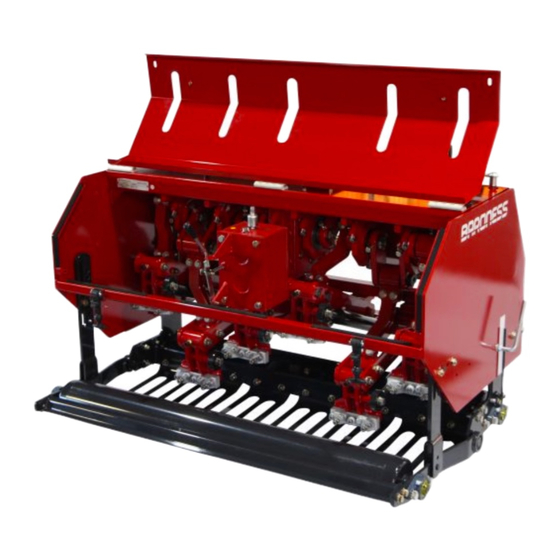
- Page 1 Tractor Mounted Aerator Service manual Serial No.20004- Ver.1.0...
- Page 2 The information described in this manual is subject to change for improvement without prior notice. When replacing parts, be sure to use genuine Baroness parts or parts designated by Kyoeisha. Note that the Baroness product warranty may not apply to defects caused by the use of parts from other companies.
-
Page 3: Table Of Contents
TDA1200/TDA1600 Contents Safety............... Page 1-1 Safe Operating Practices........Page 1-2 Safety Signs and Instruction Signs....Page 1-5 Disposal............Page 2-1 Waste Disposal..........Page 2-2 Maintenance standards and maintenance..Page 3-1 Unit conversion..........Page 3-2 Tightening torques.......... Page 3-4 Lifting.............. Page 3-7 Greasing............Page 3-8 Operating Machine and Mower Units....Page 4-1... - Page 4 TDA1200/TDA1600 Contents...
-
Page 5: Safety
TDA1200/TDA1600 Safety Safe Operating Practices....... Page 1-2 Training...........Page 1-2 Preparation..........Page 1-2 Driving.............Page 1-3 Maintenance and storage....... Page 1-4 Safety Signs and Instruction Signs..Page 1-5 About Safety Signs and Instruction Signs............Page 1-5 Page 1-1... -
Page 6: Safe Operating Practices
TDA1200/TDA1600 Safety Failure to adequately follow these safety Lack of awareness of the effect of precautions may cause an accident resulting in ground conditions, especially slopes injury or death. Incorrect hitching and load distribution Never allow children or people unfamiliar... -
Page 7: Driving
TDA1200/TDA1600 Safety Replace all fuel tanks and container caps Never operate the machine with guards, securely. shields damaged, or without safety protective devices in place. Check that operator's presence controls, Be sure not to remove the interlock system. safety switches and shields are attached and Make necessary adjustments before using functioning properly. -
Page 8: Maintenance And Storage
TDA1200/TDA1600 Safety When using attachments, never direct the If the engine is provided with a shut-off discharge at bystanders valve, shut off valve while storing or or allow anyone near the machine while it is transporting. operating. Do not store any fuel near fire. -
Page 9: Safety Signs And Instruction Signs
TDA1200/TDA1600 Safety Be sure not to repair them by bending and stretching them or welding them. Keep hands and feet away from moving parts. Do not make any adjustments with the engine running. Charge batteries in an open and well ventilated area, away from any spark and flames. -
Page 10: Safety Signs And Instruction Signs
TDA1200/TDA1600 Safety Page 1-6 Safety Signs and Instruction Signs... -
Page 11: Disposal
TDA1200/TDA1600 Disposal Waste Disposal........Page 2-2 About the Waste disposal....... Page 2-2 Page 2-1... -
Page 12: Waste Disposal
TDA1200/TDA1600 Disposal Waste Disposal About the Waste disposal Make sure that waste generated when servicing or repairing the machine is disposed of in accordance with local regulations. (e.g. waste oil, antifreeze batteries, rubber products, and wires etc.) Page 2-2 Waste Disposal... -
Page 13: Maintenance Standards And Maintenance
TDA1200/TDA1600 Maintenance standards and maintenance Unit conversion........Page 3-2 Inch–millimeter conversion table.... Page 3-2 US unit–SI unit conversion table.....Page 3-3 Tightening torques......... Page 3-4 Standard tightening torques....Page 3-4 Principal tightening torques ....Page 3-5 Lifting............Page 3-7 Lifting point..........Page 3-7 Lifting point and jack stand point.... -
Page 14: Unit Conversion
TDA1200/TDA1600 Maintenance standards and maintenance Unit conversion Inch–millimeter conversion table 1 mm = 0.03937 in 1 in = 25.4 mm Fractions Decimals Fractions Decimals 1/64 0.015625 0.397 33/64 0.515625 13.097 1/32 0.03125 0.794 17/32 0.53125 13.494 3/64 0.046875 1.191 35/64 0.546875... -
Page 15: Us Unit-Si Unit Conversion Table
TDA1200/TDA1600 Maintenance standards and maintenance US unit–SI unit conversion table To Convert Into Multiply By Miles Kilometers 1.609 Yards Meters 0.9144 Feet Meters 0.3048 Linear Measurement Feet Centimeters 30.48 Inches Meters 0.0254 Inches Centimeters 2.54 Inches Millimeters 25.4 mile Square Miles Square Kilometers 2.59... -
Page 16: Tightening Torques
TDA1200/TDA1600 Maintenance standards and maintenance Tightening torques Standard tightening torques Bolts and Nuts Important A number of bolts are used in each part of this machine. Be sure to re-tighten the bolts and nuts, because they may be loosened at the earlier stage of the use. -
Page 17: Principal Tightening Torques
TDA1200/TDA1600 Maintenance standards and maintenance Heat-treated bolt Strength classification 8.8 Strength classification 10.9 Nominal diameter 10.9 tib3yb-002 tib3yb-003 kgf-cm lb-in kgf-cm lb-in 5 - 7 50.99 - 71.38 44.26 - 61.96 7 - 10 71.38 - 101.97 61.96 - 88.51 8 - 11 81.58 - 112.17... - Page 18 TDA1200/TDA1600 Maintenance standards and maintenance Tightening torque Thread Location Code number Part name locking kgf-cm lb-in adhesive 920.71 - K0013120702 Bolt, heat-treated M12-70 104 - 134 1060.8 - 1366.8 ○ 1186.31 2655.91 - TDA12000362Z8 Nut M20-A 300 - 350 3060 - 3570 ―...
-
Page 19: Lifting
TDA1200/TDA1600 Maintenance standards and maintenance Lifting Front frame Rear frame Lifting point Lifting point Sling Warning Jack-stand points When repairing the front roller or any parts Rear frame pipe related to the roller, place the machine on a solid flat floor such as concrete and remove... -
Page 20: Greasing
TDA1200/TDA1600 Maintenance standards and maintenance Greasing No. of Location Greasing About Greasing Points Rear roller Since there may be adhesion or damage due Front roller to lack of grease on moving parts, they must be greased. Clutch Add urea-based No. 2 grease in accordance Journal cross with the Maintenance Schedule. - Page 21 TDA1200/TDA1600 Maintenance standards and maintenance Clutch Slide (inner/outer tubes) Use lithium grease (urea type) with Pull out the slide and apply grease. molybdenum. 8bq62b-216 Greasing points_004 Journal cross Use lithium grease (urea type) with molybdenum. One location in each journal cross.
- Page 22 TDA1200/TDA1600 Maintenance standards and maintenance Page 3-10 Greasing...
-
Page 23: Operating Machine And Mower Units
TDA1200/TDA1600 Operating Machine and Mower Units Maintenance..........Page 4-2 About Maintenance.........Page 4-2 Specifications......... Page 4-3 Crank timing diagram......Page 4-3 Grease............ Page 4-4 Oil............Page 4-4 Special Tool..........Page 4-5 List of Special Tools........Page 4-5 Removal and installation of each section............. Page 4-7 φ12.φ18 tine mounting board.... -
Page 24: Maintenance
Operating Machine and Mower Units Maintenance About Maintenance This chapter describes primary checking and maintenance operations for TDA1200/1600. For information on daily checks, maintenance and handling of the machine, please refer to the separate TDA1200/1600 Owner's Operating Manual and Parts Catalog. -
Page 25: Specifications
TDA1200/TDA1600 Operating Machine and Mower Units Specifications Crank timing diagram TDA1200 View from the back Timing Left View from the left side 35gcfm-001 Crank timing diagram_001 Page 4-3 Specifications... -
Page 26: Grease
TDA1200/TDA1600 Operating Machine and Mower Units TDA1600 View from the back Timing Left View from the left side 35gcfm-002 Crank timing diagram_002 Grease Use the following type of grease on the operating machine and mower units. Grease Excelite EP No. 2 (urea type) Use the following type of grease on the drive shaft. -
Page 27: Special Tool
TDA1200/TDA1600 Operating Machine and Mower Units Special Tool List of Special Tools 6209 Bearing driver Used when installing bearings with K4802000912 outer Φ85 and inner Φ45 q9c6v6-009 6204 Bearing driver Used when installing bearings with K4802000762 outer Φ47 and inner Φ20... - Page 28 TDA1200/TDA1600 Operating Machine and Mower Units 6205 Bearing driver Used to knock-in and install the K4802000822 bearing of outer φ52 and inner φ25 q9c6v6-009 6206 Bearing driver Used when installing bearings with K4802000832 outer φ62 and inner φ30 q9c6v6-009 Page 4-6...
-
Page 29: Removal And Installation Of Each Section
TDA1200/TDA1600 Operating Machine and Mower Units Install the socket on the spinner handle, Removal and installation of each and remove the two bolts and the section φ12.φ18 tine mounting board. φ12.φ18 tine mounting board Removal of φ12.φ18 tine mounting board... -
Page 30: Lower Housing Assy
TDA1200/TDA1600 Operating Machine and Mower Units Installation of φ12.φ18 tine mounting board Removal of lower housing Assy Caution Warning Refer to "Tightening torques" (Page 3-4) . When removing or installing any crank parts, Note that the Baroness product warranty may be sure to secure the crank. - Page 31 TDA1200/TDA1600 Operating Machine and Mower Units Remove the lower housing Assy set at the Caution lowest point in the following procedure: Nuts shall be tighten until locking is released. Loosen the nuts of the bolts which are connecting the crank housing with the lower housing Assy.
-
Page 32: Spring Box
TDA1200/TDA1600 Operating Machine and Mower Units Loosen the rope and lower the lower Installation of lower housing Assy housing Assy slowly. Caution Refer to "Tightening torques" (Page 3-4) . Note that the Baroness product warranty may not apply to any defects caused by incorrect or overtorque tightening, etc. -
Page 33: Crank Assy
TDA1200/TDA1600 Operating Machine and Mower Units Remove the spring box at the lowest point Box mounting bracket in the following procedure: Bolt Spring box When removing the spring box after that, attach the sling to the crank housing at the... - Page 34 TDA1200/TDA1600 Operating Machine and Mower Units Loosen all drive shaft nuts. Removal of crank Assy Warning When removing or installing any crank parts, be sure to secure the crank. If the crank is not secured, the crank may become unbalanced and rotate suddenly.
- Page 35 There are four and six fixing points in or overtorque tightening, etc. TDA1200 and TDA1600, respectively. Prepare the left crank Assy in according with the following procedure. (See "Crank Assy layout" (Page 4-11) .) Temporarily tighten each nut.
- Page 36 TDA1200/TDA1600 Operating Machine and Mower Units Install the sling on the left crank Assy in the Install housing mounting bracket A with position shown in the figure, and lift the bolts, spring washers, and washers at two sling with using a hoist, etc.
- Page 37 TDA1200/TDA1600 Operating Machine and Mower Units Insert the upper housing between crank Tighten all of the other slotted nuts which bracket A and gear box-side crank bracket, have been tightened temporarily on the and insert the crank shaft. specified torque. (See "Crank Assy layout"...
-
Page 38: Gearbox
TDA1200/TDA1600 Operating Machine and Mower Units Gearbox Gearbox Upper arm Gear box layout Slotted nut and cotter pin Caution When removing and installing the crank nuts, be sure to secure the crank. Secure the crank bracket by using a wood block, etc. - Page 39 TDA1200/TDA1600 Operating Machine and Mower Units Pull out the left and right crank shafts from Remove the crank brackets from the drive the crank brackets. shaft by using a pulley puller. Remove the one in the opposite side as well in the same procedure.
- Page 40 TDA1200/TDA1600 Operating Machine and Mower Units Set sling A to the left and right sides of the Gearbox drive shaft and sling B to the neck of the Housing mounting board gear box so that the gear box can be lifted Bolt and spring washer with keeping its stability.
- Page 41 TDA1200/TDA1600 Operating Machine and Mower Units Lift the gear box with the slings. Bolt and U nut Washer Collar Tighten the housing mounting board with bolts, spring washers, and washers on the specific torque. c8hvyh-001 Installation of gear box_001 Gearbox...
-
Page 42: Front Roller Assy
TDA1200/TDA1600 Operating Machine and Mower Units Tighten the left and right crank bracket with Front Roller Assy bolts, nuts, and spring washers. Removal of front roller Assy Install the upper housing Assy between the crank brackets and drive in the crank shaft. -
Page 43: Rear Roller Assy
TDA1200/TDA1600 Operating Machine and Mower Units Remove the bolt and spring washer. Installation of front roller Assy Follow the same steps to remove those on the other side. Caution Refer to "Tightening torques" (Page 3-4) . Note that the Baroness product warranty may not apply to any defects caused by incorrect or overtorque tightening, etc. - Page 44 TDA1200/TDA1600 Operating Machine and Mower Units Loosen the hollow set securing the roller Pulley puller shaft of the flange unit. Flange unit Follow the same steps to loosen the one on the opposite side. Remove snap pin A and the flat-head pin securing the rear roller bracket (R).
-
Page 45: Front Roller Bracket
TDA1200/TDA1600 Operating Machine and Mower Units Remove the rear roller by sliding it to the Remove snap pin A and the flat-head pin right. securing the rear roller Assy. Follow the same steps to remove those on the other side. - Page 46 TDA1200/TDA1600 Operating Machine and Mower Units Place the jack stands under the rear frame Sling pipe. Bolt and spring washer Front roller Assy Flange unit Grass pressing mounting bracket Bolt, spring washer, and washer Place the jack stands in the box mounting bracket.
-
Page 47: Inspection And Repair Of Each Section
TDA1200/TDA1600 Operating Machine and Mower Units Remove the bolt and spring washer from Remove the roller stopper and fastening the tine holder and then remove the spring plate together while holding the front roller box. bracket. Note: It makes it easier to remove the right front roller bracket. - Page 48 TDA1200/TDA1600 Operating Machine and Mower Units Remove U nuts B and washers from 3 Inspection of lower housing Assy palces on the arm axis, and then remove the lower arm. ■ TDA1200 Wear of bearings due to frequent usage and invasion of water may damage bearings, etc., preventing smooth rotation of the tine...
- Page 49 TDA1200/TDA1600 Operating Machine and Mower Units Remove the tine holder, lower housing A, Remove bearings from the lower housing and lower housing B, and then remove the A (with a bearing) and the lower housing B collar. (with a bearing), too.
- Page 50 TDA1200/TDA1600 Operating Machine and Mower Units Drive the tine holder, lower housing A and Important lower housing B by using a driver tool. Install the bearing collars with taking care of their correct directions. Insert the bearing collars into each appropriate arm axis.
- Page 51 TDA1200/TDA1600 Operating Machine and Mower Units Tighten the arm axies by using a disc Important spring and U nut. Install the bearing collars with taking care of their correct directions. Insert the bearing colors into the lower housing A, lower housing B and tine holder.
- Page 52 TDA1200/TDA1600 Operating Machine and Mower Units Remove U nuts B and washers from 2 TDA1600 ■ places on the arm axis, and then remove the lower arm. Wear of bearings due to frequent usage and invasion of water may damage bearings, etc., preventing smooth rotation of the tine...
- Page 53 TDA1200/TDA1600 Operating Machine and Mower Units Strike the arm axis by using a wood Remove the U nut and washer, and push hummer to remove it, and then remove the the bolt down to the face of tine holder lower housing B, collar, bearing, and Assy.
- Page 54 TDA1200/TDA1600 Operating Machine and Mower Units Remove the bolt from the time holder A. Bearing collar Arm axis Lock plate Fasten the lower housing A on a vice, and then remove its bearing. Follow the same steps to remove a bearing from the other side.
- Page 55 TDA1200/TDA1600 Operating Machine and Mower Units Drive the lower housing B by using a Important driver tool, and then insert its collar. Install the bearing collars with taking care of their correct directions. Insert bearing collars in each arm axis.
- Page 56 TDA1200/TDA1600 Operating Machine and Mower Units Install the arm axis and bearing collar on Drive the lower housing A by using a the other side of the lock plate, and then driver tool, and then insert its collar. drive the tine holder A by using a driver tool.
- Page 57 TDA1200/TDA1600 Operating Machine and Mower Units Install the tine holder B onto the arm axis Install the lower arm. and the bolt, and then drive the tine holder B horizontally by using a driver tool. iiprkx-023 TDA1600_023 iiprkx-021 Lower arm...
-
Page 58: Spring Box
Confirm that the compression spring is not ・ broken nor shrunk. Note: Between the spring box Assys of TDA1200 and TDA1600, the spring box, compression box, and spring shaft varies, but the assembling and inspection methods are the pue9kj-003 same. - Page 59 TDA1200/TDA1600 Operating Machine and Mower Units Loosen the nut and spring washer of the Remove the spiral pin from the spring hollow set securing the fastening bracket to stopper. the spring box, and remove the hollow set. pue9kj-008 pue9kj-005 Inspection of spring box_008...
- Page 60 TDA1200/TDA1600 Operating Machine and Mower Units Confirm that there is no abnormality in the Confirm that there is no abnormality in the spring shaft, compression spring, fastening spring box, hollow set, spring washer, nor bracket, and spring stopper. nut. Note: Replace the urethane sheet with a new one.
- Page 61 TDA1200/TDA1600 Operating Machine and Mower Units Adjust the hole for the pin of the spring Insert the spring shaft Assy into the spring stopper to the hole of the spring shaft and box. drive the spiral pin into the hole.
-
Page 62: Crank Assy
TDA1200/TDA1600 Operating Machine and Mower Units Drive the bearing by using a driver and Crank Assy install the stop rings to both sides of it. Inspection of crank Assy Push the urethane collar into the bearing. Wear of bearings due to frequent usage and invasion of water may damage bearings etc. - Page 63 TDA1200/TDA1600 Operating Machine and Mower Units Loosen the nut and remove the bolt. Open the angle between the crank bracket Follow the same steps to remove the bolt and crank bracket A by using the crank from the other side.
- Page 64 TDA1200/TDA1600 Operating Machine and Mower Units Knock the crank shaft by using a wooden Upper housing hammer to pull it out up to the crank Bearing and collar bracket face. Important Be sure to replace the bearings, disc springs and cotter pins with new ones.
- Page 65 TDA1200/TDA1600 Operating Machine and Mower Units Drive in the upper housing by using a Install the crank bracket into the crank driver. shaft. ogzg3t-012 ogzg3t-015 Inspection of crank Assy_012 Inspection of crank Assy_015 Upper housing Crank bracket Insert the collar.
-
Page 66: Crank Housing
TDA1200/TDA1600 Operating Machine and Mower Units Drive it in by using a wooden hammer to Disc spring prevent any damage on the thread. Slotted nut Bolt, nut, and spring washer Install two bolts, nuts, and spring washers, tighten them until the bolts hit the keys, and lock them with nuts. - Page 67 TDA1200/TDA1600 Operating Machine and Mower Units Remove the stop ring from the crank Remove the drive shaft by striking it with a housing. wooden hummer to prevent any damage on the shaft. t9b58o-001 t9b58o-003 Inspection of crank housing_001 Inspection of crank housing_003...
-
Page 68: Rear Roller Bracket Assy
TDA1200/TDA1600 Operating Machine and Mower Units Remove the stop ring securing the rear Rear roller bracket Assy roller bracket. Inspection of rear roller bracket Assy Wear of bearings due to frequent usage and invasion of water may damage bearings etc. - Page 69 TDA1200/TDA1600 Operating Machine and Mower Units Remove the bearing by using a driver. Important Be sure to use a driver when driving in a bearing. Be sure to replace the bearing with new one. Drive in the bearing by using a driver and install the stop ring.
- Page 70 TDA1200/TDA1600 Operating Machine and Mower Units Page 4-48 Inspection and repair of each section...
-
Page 71: Reference
TDA1200/TDA1600 Reference Specifications......... Page 5-2 Maintenance Schedule......Page 5-3 List of Consumables......Page 5-4 Page 5-1... -
Page 72: Specifications
TDA1200/TDA1600 Reference Specifications *The specifications of the tractor are different Model TDA1200 TDA1600 Total length 97 cm (38.19 in) 97 cm (38.19 in) Dimensions Total width 142 cm (55.91 in) 179 cm (70.47 in) Total height 85 cm (33.46 in) 85 cm (33.46 in) -
Page 73: Maintenance Schedule
TDA1200/TDA1600 Reference Maintenance Schedule TDA1200/1600 Follow the maintenance schedule below. Caution Use tools appropriate for each maintenance operation. ○···Inspect, adjust, supply, clean ●···Replace (first time) △···Replace Maintenance Item Tightening the parts ○ Tine ○ Operating depth ○ Greasing, oiling ○... -
Page 74: List Of Consumables
TDA1200/TDA1600 Reference List of Consumables The consumables are described below. Caution Use tools appropriate for each replacement operation. TDA1200 Code Part name Qty. Remarks Spring box Assy TDA12000373Z0 Spring box Assy φ12φ18 tine mounting Standard tine mounting board TDA12000325A2 board... - Page 75 Head Office 1-26, Miyuki-cho, Toyokawa, Tel : (0533) 84 - 1390 Fax : (0533) 89 - 3623 Aichi-Pref. 442-8530 Japan. TDA1200-SM--GBZ/14L-00-S.K...
Need help?
Do you have a question about the TDA1200 and is the answer not in the manual?
Questions and answers